Zephyr PS GPIO Driver Implementation
This page provides details on the implementation of the PS GPIO Zephyr driver.
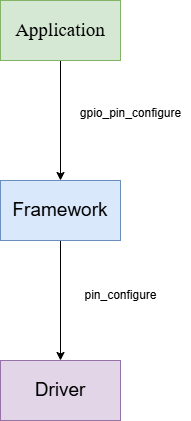
GPIO Layers
The gpio driver does not use a subsystem. Instead, the
Zephyr GPIO framework
header (gpio.h) validates the parameters passed and calls the
driver API.
PS/PMC GPIO Node
Node
PMC GPIO DTS
============

psgpio: gpio@f1020000 {
        compatible = "xlnx,ps-gpio";
        status = "disabled";
        reg = <0xf1020000 0x1000>;
        interrupts = <GIC_SPI 180 IRQ_TYPE_LEVEL
                        IRQ_DEFAULT_PRIORITY>;
        interrupt-names = "irq_0";

        #address-cells = <1>;
        #size-cells = <0>;

        psgpio_bank0: psgpio_bank@0 {
                compatible = "xlnx,ps-gpio-bank";
                reg = <0x0>;
                gpio-controller;
                #gpio-cells = <2>;
                ngpios = <26>;
                status = "okay";
        };

        psgpio_bank1: psgpio_bank@1 {
                compatible = "xlnx,ps-gpio-bank";
                reg = <0x1>;
                gpio-controller;
                #gpio-cells = <2>;
                ngpios = <26>;
                status = "okay";
        };

        psgpio_bank3: psgpio_bank@3 {
                compatible = "xlnx,ps-gpio-bank";
                reg = <0x3>;
                gpio-controller;
                #gpio-cells = <2>;
                ngpios = <32>;
                status = "okay";
        };

        psgpio_bank4: psgpio_bank@4 {
                compatible = "xlnx,ps-gpio-bank";
                reg = <0x4>;
                gpio-controller;
                #gpio-cells = <2>;
                ngpios = <32>;
                status = "okay";
        };
};


PS GPIO DTS
===========

psgpio: gpio@f19d0000 {
        compatible = "xlnx,ps-gpio";
        status = "disabled";
        reg = <0xf19d0000 0x1000>;
        interrupts = <GIC_SPI 20 IRQ_TYPE_LEVEL
                        IRQ_DEFAULT_PRIORITY>;
        interrupt-names = "irq_0";

        #address-cells = <1>;
        #size-cells = <0>;

        psgpio_bank0: psgpio_bank@0 {
                compatible = "xlnx,ps-gpio-bank";
                reg = <0x0>;
                gpio-controller;
                #gpio-cells = <2>;
                ngpios = <26>;
                status = "okay";
        };

        psgpio_bank3: psgpio_bank@3 {
                compatible = "xlnx,ps-gpio-bank";
                reg = <0x3>;
                gpio-controller;
                #gpio-cells = <2>;
                ngpios = <32>;
                status = "okay";
        };
};
Probe Data From Node
In driver we need to assign the compatible string to a zephyr macro,
DT_DRV_COMPAT. If the assigned string matched with any one of the DT nodes
along with status property okay then driver need to register the driver API to
the GPIO framework using a framework structure.
Probe PS/PMC GPIO NODE
#define GPIO_XLNX_PS_DEV_INITITALIZE(idx)\
GPIO_XLNX_PS_GEN_BANK_ARRAY(idx)\
GPIO_XLNX_PS_DEV_CONFIG_IRQ_FUNC(idx)\
GPIO_XLNX_PS_DEV_DATA(idx)\
GPIO_XLNX_PS_DEV_CONFIG(idx)\
GPIO_XLNX_PS_DEV_DEFINE(idx)

DT_INST_FOREACH_STATUS_OKAY(GPIO_XLNX_PS_DEV_INITITALIZE);
DT_DRV_COMPAT
This macro holds the compatible string of the driver “
xlnx_ps_gpio”
DT_INST_FOREACH_STATUS_OKAY
This macro calls “
GPIO_XLNX_PS_DEV_INITITALIZE(idx)” on all node with compatible “DT_DRV_COMPAT” and status “okay”
GPIO_XLNX_PS_GEN_BANK_ARRAY
This creates an array of device structure which holds all the child nodes(psgpio_bank<X>) device structure.
GPIO_XLNX_PS_DEV_CONFIG_IRQ_FUNC
This declare a definition of irq registration function.
GPIO_XLNX_PS_DEV_DATA
This declares a device specific data structure
gpio_xlnx_ps_dev_data.
GPIO_XLNX_PS_DEV_CONFIG
This declare a device specific config structure “
gpio_xlnx_ps_dev_cfg” and initialize them.
GPIO_XLNX_PS_DEV_DEFINE
This macro creates a device object during kernel system init.
gpio_xlnx_ps_initAPI is run by the kernel during system initialization.
gpio_xlnx_ps_init
Call irq configure.
Probe PS/PMC GPIO BANK NODE
#define GPIO_XLNX_PS_BANK_INIT(idx)\
static const struct gpio_xlnx_ps_bank_dev_cfg gpio_xlnx_ps_bank##idx##_cfg = {\
        .common = {\
                .port_pin_mask = GPIO_PORT_PIN_MASK_FROM_DT_INST(idx),\
        },\
        .base_addr = DT_REG_ADDR(DT_PARENT(DT_INST(idx, DT_DRV_COMPAT))),\
        .bank_index = DT_INST_REG_ADDR(idx),\
};\
static struct gpio_xlnx_ps_bank_dev_data gpio_xlnx_ps_bank##idx##_data;\
DEVICE_DT_INST_DEFINE(idx, gpio_xlnx_ps_bank_init, NULL,\
        &gpio_xlnx_ps_bank##idx##_data, &gpio_xlnx_ps_bank##idx##_cfg,\
        PRE_KERNEL_1, CONFIG_GPIO_INIT_PRIORITY, &gpio_xlnx_ps_bank_apis);

DT_INST_FOREACH_STATUS_OKAY(GPIO_XLNX_PS_BANK_INIT);
gpio_xlnx_ps_bank_apisis a structure variable where we add all the api that need to be registered to framework.
gpio_xlnx_ps_bank_init
Disable interrupt and status register.
make all GPIO pins as input and make data as 0.
GPIO Framework
GPIO framework has a structure where drivers need to register their APIs by following the same protocol used in the structure that follows,
Freamework Structure
__subsystem struct gpio_driver_api {
        int (*pin_configure)(const struct device *port, gpio_pin_t pin,
                             gpio_flags_t flags);
#ifdef CONFIG_GPIO_GET_CONFIG
        int (*pin_get_config)(const struct device *port, gpio_pin_t pin,
                              gpio_flags_t *flags);
#endif
        int (*port_get_raw)(const struct device *port,
                            gpio_port_value_t *value);
        int (*port_set_masked_raw)(const struct device *port,
                                   gpio_port_pins_t mask,
                                   gpio_port_value_t value);
        int (*port_set_bits_raw)(const struct device *port,
                                 gpio_port_pins_t pins);
        int (*port_clear_bits_raw)(const struct device *port,
                                   gpio_port_pins_t pins);
        int (*port_toggle_bits)(const struct device *port,
                                gpio_port_pins_t pins);
        int (*pin_interrupt_configure)(const struct device *port,
                                       gpio_pin_t pin,
                                       enum gpio_int_mode, enum gpio_int_trig);
        int (*manage_callback)(const struct device *port,
                               struct gpio_callback *cb,
                               bool set);
        uint32_t (*get_pending_int)(const struct device *dev);
#ifdef CONFIG_GPIO_GET_DIRECTION
        int (*port_get_direction)(const struct device *port, gpio_port_pins_t map,
                                  gpio_port_pins_t *inputs, gpio_port_pins_t *outputs);
#endif /* CONFIG_GPIO_GET_DIRECTION */
};
Functional Implementation
pin_configure
Configure gpio pin as input or output based on user input.
In case of output mode configuration, based on user input output value is set.
port_get_raw
Read
DATA\_<X>register.
port_set_masked_raw
Clear masked bits and write value into
DATA\_<X>register.
port_set_bits_raw
Write 1 into
DATA\_<X>register.
port_clear_bits_raw
Write 0 into
DATA\_<X>register.
port_toggle_bits
Toggle bits in
DATA\_<X>register.
pin_interrupt_configure
Disable interrupt or enable interrupt for a particular pin.
Configure interrupt type as level based or edge based trigger.
In case of edge based trigger we can further configure as rising edge or falling edge and both.
In case of level based we can further configure as rising 1 or falling 0 but not both.
Enable interrupt clear the pending INT_STAT register and then enable the interrupt.
manage_callback
Register the call back to get called when interrupt is triggered for a particular pin.
get_pending_int
Read
INT_STAT\_<X>register value and clear the same register.