Hardware Application Development
This page walks through Hardware Application Development: generating PL payloads compatible with the prebuilt EDF image through Segmented Configuration so they can be loaded or reloaded from Linux at runtime, with payload content, compatibility checking against the base or parent Vivado project, and the firmware-bundle build steps. See Development Flows for how this persona fits with the others.
Overview
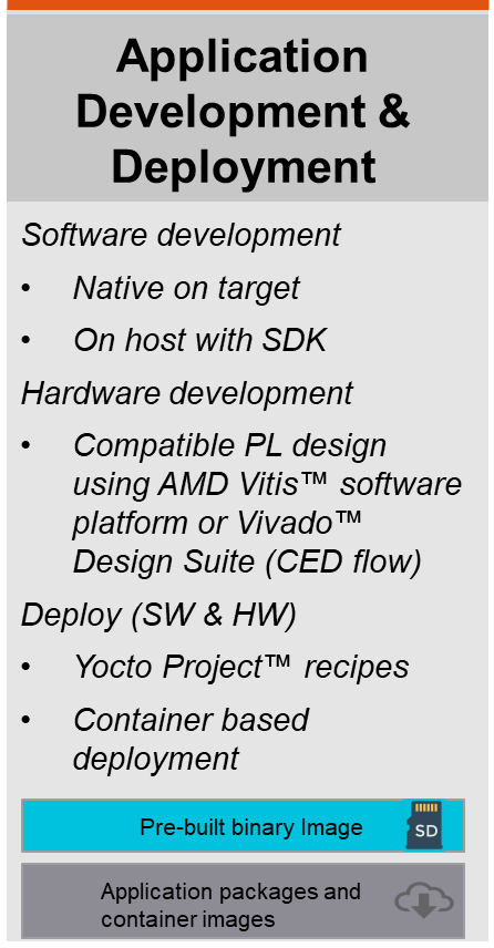
Application Development and Deployment persona summary card.
Custom RTL or hardware design is a key part of the value of adaptive SoC and FPGA devices.
This section shows to generate PL images (payloads) that are compatible with a base design such as the EDF prebuilt disk images and OSPI boot images using Segmented Configuration. See also Common Specifications
These flows enable different payloads (PL or other) to be deployed to a board and then loaded or re-loaded from Linux at runtime, speeding up development (by testing on a running system) and enabling dynamic payload management on deployed systems with Linux / U-boot as the system manager (for example version management, fallback, recovery).
This example is based on and compatible with the Embedded Common Platform CED design which is the Vivado design used to create the EDF BSP’s, the EDF prebuilt OSPI firmware and EDF Linux Disk images.
The Tcl scripts to build a compatible PL payload through a scripted flow are available here (See relevant directory for your Evaluation board): https://github.com/Xilinx/amd-yocto-hw-platforms/tree/xilinx_v2026.1/eval_board_examples/vek385_axi_uartlite
The flow to re-generate the base image (which this payload is compatible with) is covered in Custom Hardware Development AMD Versal device portfolio
PL Design / Payload Content:
The PL IP example application has the below IPs:
AXI UARTLITE
The block design is shown in the following figure, and can be viewed in Vivado after generation.
See Custom Hardware Development AMD Versal device portfolio for instructions on how to open the Vivado project from the xpr file and view a block design.
The steps to generate this compatible design are similar to the steps used when generating the base design, and use the XPR and XSA from the base design as inputs.
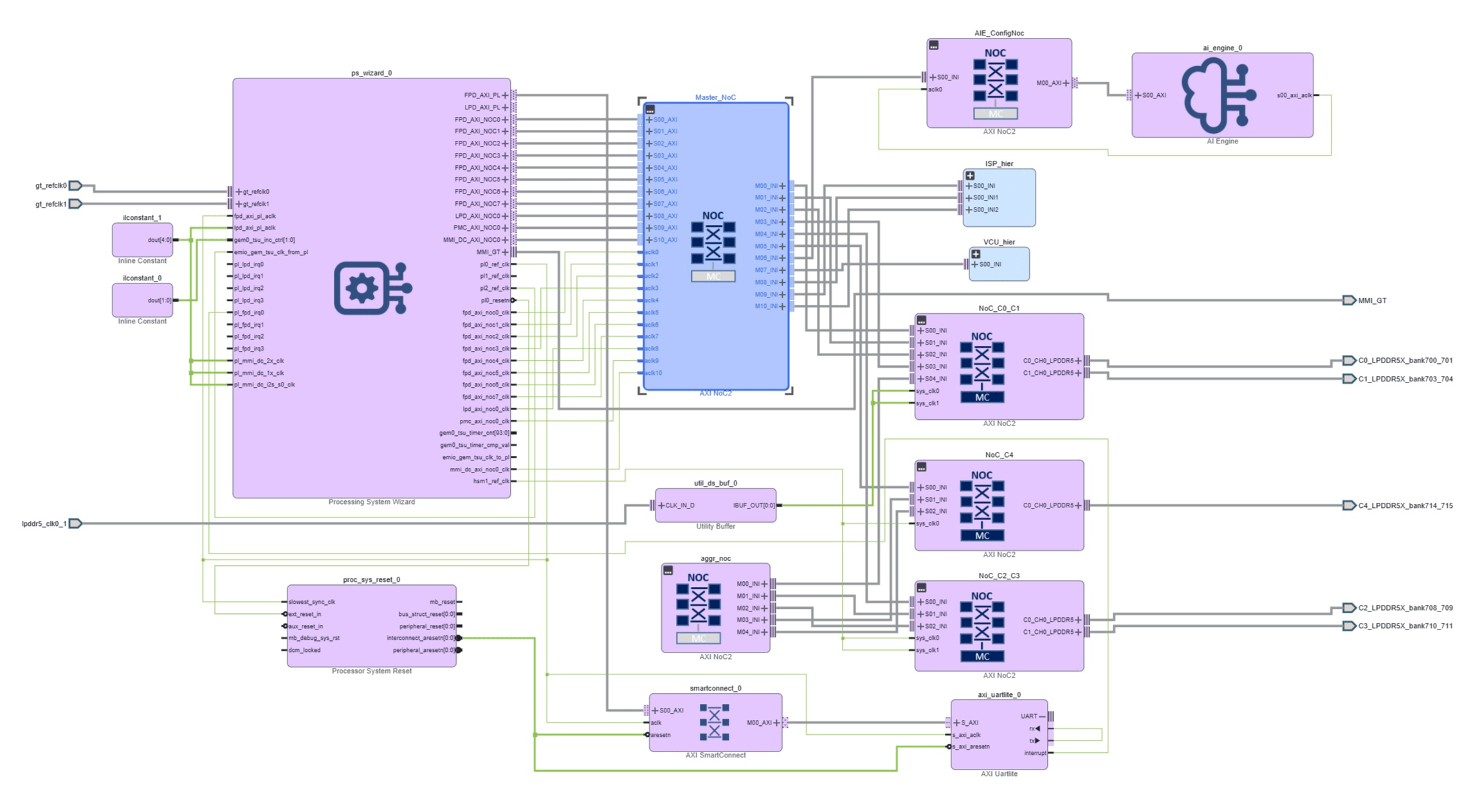
VEK385 AXI UARTLITE PL design block diagram as opened
in Vivado, showing the child design’s added axi_uartlite_0
wired through smartconnect_0 and proc_sys_reset_0 to the
ps_wizard_0 FPD_AXI_PL interface on top of the collapsed
edf_base hierarchical block. The AXI BRAM
and AXI GPIO peripherals are inherited from the
edf_base template and are not expanded in this view. Open
the hierarchical block in Vivado to inspect them.
Maintaining and Checking Compatibility of a Generated PL Firmware Application (Child Design) With the base/parent Vivado Project
Compatibility is enabled and verified through the Segmented Configuration workflows in Vivado, using some files created when the base / parent project was compiled.
See the following pages for more information on Segmented Configuration
NoC Solution File (.ncr) From Base Project
The child project must include the golden NoC solution file from the base / parent project; this allows Vivado to implement a compatible NoC solution in the child project. The NoC solution file or NCR file (.ncr) is generated during compilation of the base / parent project and should be stored.
The NCR file for the embedded common platform CEDs used in EDF BSP hardware designs is stored as part of the CED, and can be found in the Vivado installation
set_property NOC_SOLUTION_FILE [file normalize <vivado installation>/data/xhub/ced/XilinxCEDStore/ced/Xilinx/IPI/Versal_gen2_platform/vek385_golden_ncr/vek385_*.ncr] [get_runs impl_1]
Post Compile UID Checks
The PDI Unique ID from the child design and PDI Unique ID from the base project / parent design (OSPI boot pdi) should be checked before loading the application.
Issue the following command on the cloned repo to check whether the PL PDI matches with boot.pdi which is part of the OSPI boot image.
$ make checkpdi
PDI_UNIQUE_ID:0xe2261acc
GOLDEN_UNIQUE_ID:0xe2261acc
UNIQUE ID MATCHED

The above check only compares the vivado base ced boot.pdi UNIQUE ID with child design boot.pdi UNIQUE ID.

Read the unique id of boot.pdi which is packed as part boot.bin/ospi.bin using the attached script.
If above PDI_UNIQUE_ID and below boot.bin/ospi.bin UNIQUE ID should match then only you can use boot.bin/ospi with child design firmware

c:`get_unique_id.sh <hardware-application-development>`

For boot.bin
$ ./get_uniqueid.sh <downloaded artifacts>/versal-2ve-2vm-vek385-sdt-seg_xilinx-bootbin/boot.bin boot.bin
Specified Boot.bin
Reading BIN file from offset: 0x0
* Unique ID of BANK offset 0x0 is 0xe2261acc

For ospi.bin
$ ./get_uniqueid.sh <downloaded artifacts>/versal-2ve-2vm-vek385-multidomain_edf-ospi/edf-ospi-versal-2ve-2vm-vek385-multidomain.bin
Reading BIN file from offset: 0x1580000
* Unique ID of BANK offset 0x1580000 is 0xe2261acc
Reading BIN file from offset: 0x87C0000
* Unique ID of BANK offset 0x87C0000 is 0xe2261acc
DCP File Check With pr_verify
We have segmented based parent and child designs. During design generation, the NoC routing is captured in dcp files. We need to ensure that the routing should be same across parent and child design.
We need to run pr_verify using dcp files as in the following example using the example Tcl file
cat pr_verify.tcl
pr_verify -initial <path to dcp from parent
design/vek385_base.runs/impl_1/versal_gen2_platform_wrapper_routed.dcp>
-additional <path to child design
dcp/vek385_axi_uartlite.runs/impl_1/versal_gen2_platform_wrapper_routed.dcp
>
Run the preceding pr_verify.tcl in Vivado batch mode as shown in the
following snippet
$ <vivado installation>/settings.sh
$ vivado
$ vivado -mode batch -s pr_verify.tcl
Building a Compatible PL Design Payload and Creating a Firmware Bundle (Device Tree Overlay)
Refer to Hardware Design Repo Overview for cloning the hardware design repo and for setting up the AMD tools.
This example can be built using the following make commands which build the
design artifacts for the BRAM/GPIO/UARTLITE example design,
which is compatible with EDF prebuilt disk image and base design for
the board. (VEK385 is shown, update paths for your evaluation board). The
makefile uses Tcl (main.tcl and gen_sdt.tcl) scripts as a part of make steps to
build the design and generate the output files
For custom designs - All steps can be done manually through the Vivado GUI and command-line utilities
See the following Custom Designs - Manual Flows section for building the compatible PL design payload and creating a firmware bundle (device tree overlay).
$ git clone https://github.com/Xilinx/amd-yocto-hw-platforms.git -b xilinx_v2026.1
$ cd amd-yocto-hw-platforms/eval_board_examples/vek385_axi_uartlite
$ source <path to Vivado Install>/Vivado/settings64.sh
$ make all JOBS=8(default JOBs will be 1 to speed up setting it to 8)
$ make gen_overlay
The generated directories are created
Vivado project directory
hw_project- The directory contains the XPR project file which can be used to open and edit the project in VivadoSDT directory
hw_project_sdt- The SDT directory is needed to generate the firmware bundleFirmware directory
<designname>-fw(VEK385 examplevek385_axi_uartlite-fw) – The firmware directory contains the pld PDI, the matching device tree overlay binary (dtbo), and a metadata json file
The generated firmware directory includes:
shell.json- This metadata file is consumed by dfx-mgrpl.dtbo- The device tree overlay binary describes the devices in the incremental hardware design. It is used by Linux to load the corresponding device drivers<design name>_pld.pdi(VEK385 example - vek385_axi_uartlite_pld.pdi) - The pld PDI is the incremental PL payload that gets loaded from Linux on top of the boot PDI
Example output (from VEK385 design)-
$ tree -L 1 vek385_axi_uartlite-fw/
vek385_axi_uartlite-fw/
├── pl.dtbo
├── pl.dtsi
├── pl.dtso
├── shell.json
└── vek385_axi_uartlite_pld.pdi
Custom Designs- Manual Flows for Building the Compatible PL Design Payload and Creating a Firmware Bundle (Device Tree Overlay)
All steps contained in the Makefile be done manually through the Vivado GUI and command-line utilities.
Create the Compatible PL design in the GUI.
Open the parent / base Vivado project in the Vivado GUI
Follow the steps in Custom Hardware Development AMD Versal device portfolio then open the design in the Vivado GUI
Create a new PL payload by modifying or extending the default PL payload - add or modify IP blocks in the block design, add custom logic, and make any other required changes.
The PS and NoC settings should not be edited; doing so may break compatibility with the prebuilt boot.pdi and / or the prebuilt EDF images, which are based on the EDF specifications.
If PS settings are edited, this moves into a full-custom flow, requiring regenerating the EDF Linux image and updating the boot.pdi
Save the updated design
Make sure the NCR file has been added to the project. See Hardware Application Development )
Generate output products and the XSA.
Validate the compatibility of the project by following the relevant preceding sections on post-compile UID checks and
pr_verifyDCP file checks.
Create the SDTgen design artifacts (hand off information)
Note: make sdt can be used build the SDTgen design artifacts from the
XSA.
$ source <path to Vivado Install>/Vivado/settings64.sh
$ sdtgen
sdtgen% set_dt_param -debug enable
sdtgen% set_dt_param -zocl enable
sdtgen% set_dt_param -dir ./hw_project_sdt
sdtgen% set_dt_param -xsa ./<xsa_name>.xsa
sdtgen% set_dt_param -board_dts versal2-vek385-revA
sdtgen% generate_sdt
Create the firmware bundle to enable dfx-mgr-client to manage multiple PL Payloads and configure the PL from Linux**
Firmware bundle - a directory containing device tree overlay (.dtbo), PL payload (.pdi) and .json file (dfx-mgr-client configuration file)
Note: make gen_overlay can be used build the firmware bundle from the
SDTGen artifacts
Create a directory to contain the files in the firmware bundle, and copy in the source *_pld.pdi file
$ mkdir -p <project name>-fw
$ cp ./hw_project_sdt/<project name>_pld.pdi <project name>-fw
Create a shell.json file in the firmware bundle directory (<project name>-fw) with the following content :
{
    "shell_type" : "XRT_FLAT",
    "num_slots": "1"
}
Use Lopper to create the Linux Device Tree from the System Device Tree
$ source <path to Vivado Install>/Vivado/settings64.sh
$ lopper --enhanced -O <project name>-fw -f ./hw_project_sdt/system-top.dts -- xlnx_overlay_dt cortexa78_0 full ./hw_project_sdt/pl.dtsi
Use Device Tree Compiler to create the device tree overlay (.dtbo)
$ source <path to Vivado Install>/Vivado/settings64.sh
$ dtc -I dts -O dtb -o <project name>-fw/pl.dtbo <project name>-fw/pl.dtsi
You now have a firmware bundle (directory) that can be transferred to the running system for use.
Deploying the PL Firmware Application Onto Target
The firmware files can be copied to the /lib/firmware/xilinx directory on
the running system for immediate use - using SCP, TFTP, or a
similar network tool, or through direct copy to the SD card. See
GitHub - Xilinx/dfx-mgr for more
information on dfx-manager.
Optionally, the firmware bundle can be packaged and included as part of the Yocto image build by writing a Yocto recipe - Application Deployment using Yocto Recipes AMD Versal device portfolio
Listing and Loading the Firmware Package (VEK385 Example):
amd-edf:/home/amd-edf# scp -r <user>@<host/ ip address>:<path to firmware directory>/vek385_axi_uartlite-fw /lib/firmware/xilinx/.
amd-edf:/home/amd-edf# sudo dfx-mgr-client -listPackage
ID accelType   Base        slotLoc Accelerator
-- ----------- ----------- ------- -----------
 1 XRT_FLAT    vek385-r... -1      vek385-revb-pl-bram-gpio-fw
 2 RPU         rpu         -1      vek385-revb-r52-0-zephyr-openamp
 3 XRT_FLAT    vek386-p... -1      vek386-pl-bram-gpio-fw
 4 XRT_FLAT    vek385_a... -1      vek385_axi_uartlite-fw
 5 XRT_FLAT    vek385-p... -1      vek385-pl-bram-gpio-fw
 6 RPU         rpu         -1      vek385-r52-0-zephyr-openamp
Note
The package list varies by image configuration.
amd-edf:/home/amd-edf# sudo dfx-mgr-client -loadByName vek385_axi_uartlite-fw
vek385_axi_uartlite-fw: Loaded with slot_handle 0

amd-edf:/home/amd-edf# sudo dfx-mgr-client -listPackage
ID accelType   Base        slotLoc Accelerator
-- ----------- ----------- ------- -----------
 1 XRT_FLAT    vek385-r... -1      vek385-revb-pl-bram-gpio-fw
 2 RPU         rpu         -1      vek385-revb-r52-0-zephyr-openamp
 3 XRT_FLAT    vek386-p... -1      vek386-pl-bram-gpio-fw
 4 XRT_FLAT    vek385_a... 0       vek385_axi_uartlite-fw
 5 XRT_FLAT    vek385-p... -1      vek385-pl-bram-gpio-fw
 6 RPU         rpu         -1      vek385-r52-0-zephyr-openamp
Running the PL axi_uartlite Example After Deploying PL Firmware
amd-edf:/home/amd-edf# dmesg | grep uartlite
[   57.267385] b0000000.serial: ttyUL0 at MMIO 0xb0000000 (irq = 59, base_baud = 0) is a uartlite
[   57.267521] uartlite b0000000.serial: Runtime PM usage count underflow!

amd-edf:/home/amd-edf# ls -l /dev/ttyUL*
crw-rw---- 1 root dialout 240, 0 May 29 22:03 /dev/ttyUL0

amd-edf:/home/amd-edf# cat /dev/ttyUL0 > output.txt &
[1] 949
amd-edf:/home/amd-edf# echo "UARTLITE_TEST" > /dev/ttyUL0 &
[2] 950
amd-edf:/home/amd-edf# tail -f output.txt
UARTLITE_TEST
UARTLITE_TEST
UARTLITE_TEST