Custom Hardware Development
This page walks through Custom Hardware Development: generating a base hardware design and its firmware package, plus application-specific designs in either AMD Vivado RTL or the AMD Vitis software platform, and the handoff artifacts the software and OS domains need to build the complete runtime image. See Development Flows for how this persona fits with the others.
Overview
A hardware developer can create one or more hardware (HW) designs, resulting in one or more firmware bundles.
The firmware bundles (boot.pdi, PL.pdi) can be integrated with or built with the OS and boot images. A software application can interact with the hardened and/or adaptive features of the hardware design.
The firmware bundles (pl.bin) can be integrated with or built with the OS and boot images. A software application can interact with the hardened and/or adaptive features of the hardware design.
We differentiate between the base HW design firmware which is baked into the boot image, and application-specific incremental HW design firmware that is loaded into the PL at Linux runtime in support of a specific application.
The following tutorials show how to generate a base HW design and its firmware package and two examples of application-specific HW designs and firmware. One is a Vivado Design Suite based design (RTL), the other a Vitis software platform-based design. We also show how to generate various handoff artifacts needed when moving from HW to the SW or OS domain.
Typically, a hardware design team provides a new custom base HW design/Vivado
Design Suite XSA that matches their product requirements, for example, a
custom board or even a static PL design if the production image has a
fixed function. The XSA is handed off to the OS development team which
then generates a new Yocto Project machine configuration based on this base
XSA using the provided sdtgen and gen-machine-conf tooling as a
starting point (see
Software Hardware Exchange Loop (SHEL) Flow).
The EDF Linux distribution (distro) can be used as a starting point for the OS build, but the end-user can also opt to use the upstream Yocto Project poky distro or their own custom distro for their final product based on their product requirements. Customizing the OS configuration might require expert knowledge. Some common items are covered here Development Flows, and there is extensive documentation available online for this purpose (https://docs.yoctoproject.org/scarthgap/singleindex.html ).
Similarly, creating and customizing a Vivado Design Suite/RTL design can require expert knowledge, and extensive documentation is available on this subject.
AMD EDF v26.06 - AMD Vivado Design Suite 2026.1
A Vitis software platform-based design is not included in this release. This is scheduled for inclusion after the AMD Vivado Design Suite 2026.1 release.
AMD EDF v26.06 - AMD Vivado Design Suite 2026.1
ZCU104 - The base design does not include a default PL payload
This is scheduled to be updated in the next release
The VCU example can be used as an example payload zcu104_pl_vcu_extensible
Custom Hardware Development persona summary card.
EDF Hardware Design Repository Overview
The following section gives an overview of the hardware design repository which provides the baseline for the Yocto Project machine configuration used in this tutorial.
$ git clone https://github.com/Xilinx/amd-yocto-hw-platforms.git -b xilinx_v2026.1
$ cd amd-yocto-hw-platforms
$ tree eval_board_base/vek385_base/
eval_board_base/vek385_base/
├── Makefile
└── scripts
    ├── gen_sdt.tcl
    └── main.tcl
Ensure you use the branch of amd-yocto-hw-platforms that matches the EDF version in use.
It’s recommended to use the latest version available.
See Downloads and Release Notes for detail on released versions.
The directory structure lists the VEK385 base design that can be built from the EDF Hardware Design repo:
<board name>_base– This is the embedded common platform CED design mapped to a target evaluation board. It enables segmented configuration which allows deployment of a common boot PDI (loaded from the primary boot device by the EDF Boot Firmware), and a PL PDI loaded at Linux runtime (deferred PL load).The embedded common platform CED includes a minimal PL payload that has some basic peripherals mapped to the evaluation board: PL UART, DIP switch, push buttons, and user LEDs via a pair of AXI GPIO controllers, and a simple BRAM controller. The PL payload firmware (PL PDI, and device tree PL .dtbo) is loaded after Linux boot from the user space.
Note
The following set of example commands are for a ZCU104 based board design. For other Zynq boards, use the appropriate board names.
$ git clone git@github.com:Xilinx/amd-yocto-hw-platforms.git -b xilinx_v2026.1
$ cd amd-yocto-hw-platforms
$ tree eval_board_base/zcu104_base/
eval_board_base/zcu104_base/
├── Makefile
└── scripts
    ├── gen_sdt.tcl
    └── main.tcl
The directory structure lists the base design that can be built from the EDF Hardware Design repo:
<board name>_base - This is the embedded common platform CED design
mapped to a target evaluation board. It enables deferred PL load
which allows for deployment of a common boot PDI (loaded from the
primary boot device by the EDF Boot Firmware) and a PL
.bin loaded at Linux runtime (deferred PL load).
A top-level Makefile is provided for easy build orchestration. Each of the preceding designs can be built with a single make command. The make command builds a series of artifacts:
The hardware design which typically ends with exporting a Vivado Design Suite XSA.
The system device tree (SDT) artifacts directory which is needed for handoff to the software build flow - Yocto Project build
A firmware (FW) bundle which is needed to dynamically load the PL designs from Linux
While the Makefile is convenient, we also provide step-by-step instructions for running the respective commands by hand.
The following design examples are compatible with the AMD Vivado Design Suite 2026.1 EA tools version.
The following design examples are compatible with the AMD Vivado Design Suite 2026.1 EA tools version.
Vivado Base Design and Base Platform
The following tutorial shows how to generate the Vivado Design Suite base design XSA from a Tcl based project and how to generate the system device tree handoff artifacts that are needed to set up the Yocto build.
Refer to EDF Hardware Design Repository Overview for details on setting up the hardware design repo and the tools.
From the top-level directory, use make to build the base design project from
Tcl. This step takes some time because it runs implementation to generate
the routed dcp which is used later by
pr_verify for checking design compatibility for segmented config
when creating alternative compatible PL payloads.
Also, the build reads a NoC solution file from the Vivado install area for the CED to re-seed the NoC solution, and checks the unique ID of boot.pdi for the prebuilt Vivado CED against the newly generated boot.pdi to confirm if it has same unique ID or not. This ensures compatibility between the prebuilt boot firmware and users who created their custom design from the Vivado CED (and can then deploy the PL image directly to a system running the re-built boot firmware and boot image).
Note
See the output directory for the .dcp file used to check for
compatibility of designs in the Segmented Configuration flow
(pr_verify).
The following command uses JOBS=8 to run 8 parallel compiles, with each
compile spawning multiple threads, where the maximum number of threads
is by default limited to the number of CPU cores detected. This
requires significant RAM and Processor resources.
For example: JOBS=8 - The number of processes = 8 x <number of
cores>, with matching RAM requirements.
If you are running on a system with limited resources, it is recommend to set
JOBS=1
$ cd eval_board_base/vek385_base
$ make all JOBS=8
$ cd eval_board_examples/zcu104_pl_vcu_extensible/
$ make all JOBS=8
Note
The above example command is for a ZCU104 board. For other Zynq boards, use the appropriate board names.
The make command generates the following artifacts inside the
base/ directory:
Project directory hw_project - The directory contains the Vivado .xpr project file which can be used to open and edit the project in the Vivado Design Suite
SDT artifacts directory hw_project_sdt - The SDT directory is used as handoff artifact to set up the Yocto Project disk image build
You can now open the generated Vivado Design Suite project to view the generated design:
Open the generated xpr project file from the command line (See the Vivado Design Suite documentation for other ways to open the project)
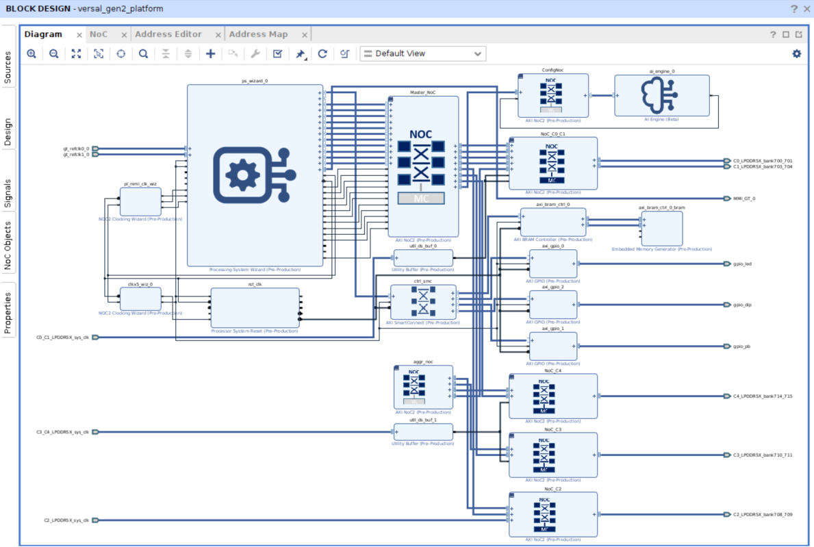
$ cd hw_project/vek385_base
$ vivado vek385_base.xpr &
Here is a screenshot of the block design:
The output of the generated sdt artifacts directory looks as follows. You can see that two different PDIs were generated for the segmented configuration flow:
boot PDI <board name>_base_boot.pdi - this PDI is used in the boot image (boot.bin) and is stored in the OSPI as a boot image to be loaded by the EDF Boot Firmware.
pld PDI <board_name>_base_pld.pdi - This is the PL PDI used to load the PL. This file is one of the input files to create the firmware bundle to load the PL from Linux userspace or U-Boot, and can be added to the rootfs build or copied directly to the running system. See Firmware Bundle and Hardware Application Development for the steps to create the firmware bundle.
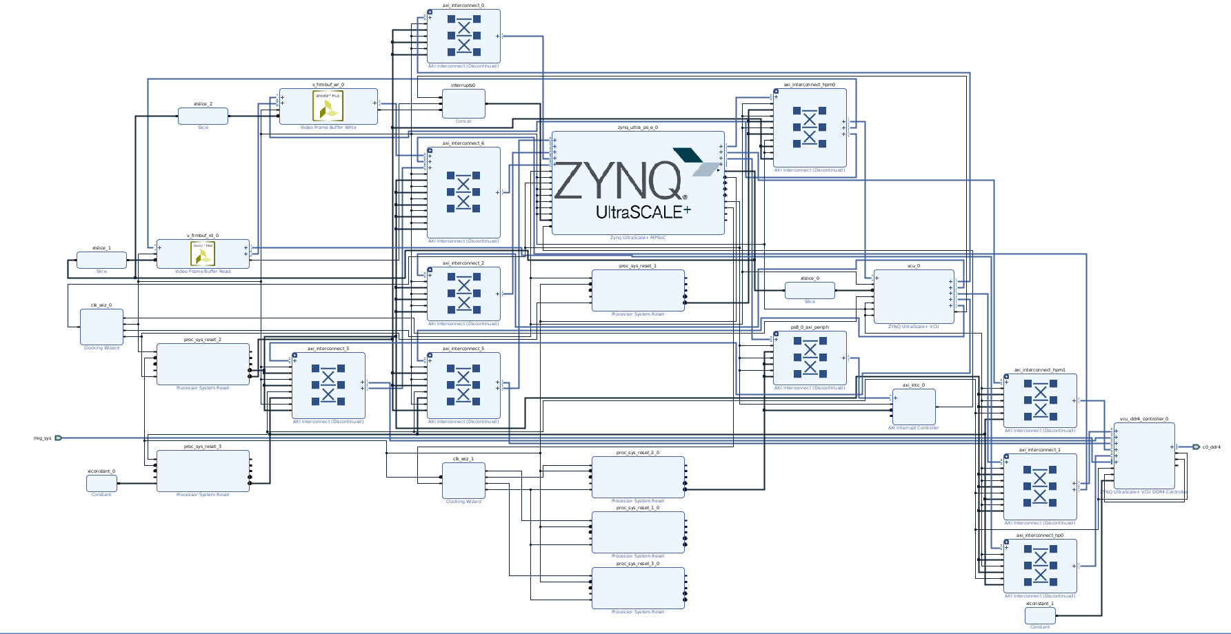
$ cd hw_project/zcu104_pl_vcu_extensible/
$ vivado zcu104_pl_vcu_extensible.xpr &
The output of the generated sdt artifacts directory looks as follows. You can see that the pl.bin file was generated for the deferred load flow:
zcu104_pl_vcu_extensible.bit - This is the PL PDI used to load the PL. This file is one of the input files to create the firmware bundle to load the PL from the Linux user space or U-Boot, and can be added to the rootfs build or copied directly to the running system. See Hardware Application Development for the steps to create the firmware bundle.
Note
Operating System Integration and Development expects the following:
SDTGen to have been run to generate a System Device Tree directory (containing the PL.:term:PDI and hardware project derived Device Trees)
<system Device Tree Directory>/pl.dtsi(PL Device Tree) to have been manually updated to reflect PL content if neededgen-machine-confto have been run to populate the Yocto Project build directory
See Segmented Configuration or Dynamic Function eXchange.
The Yocto Project build recipes (created by recipetool-create)
then handle the file conversion, Device Tree Overlay, and integration
into the root fs as part of the Image build process
The firmware package can also be created manually, and copied directly to the running image for testing using SCP, tftp, or through SD Card.
SDTGen is run as part of the build process in the Makefile, the contents of the System Device Tree Handoff Directory are shown in the following listing.
It contains a series of device tree files with system-top.dts
being the top-level device tree.
$ tree -L 1 hw_project_sdt/
hw_project_sdt/
├── aie_primitive.json
├── extracted
├── HashBlock0.bin
├── include
├── pcw.dtsi
├── pl.dtsi
├── system-top.dts
├── vek385_base_boot.pdi
├── vek385_base.isd
├── vek385_base.mmi
├── vek385_base_pld.pdi
├── versal2-clk-ccf.dtsi
├── versal2.dtsi
└── versal2-vek385-revA.dtsi
The following tutorial shows the steps for generating the sdt handoff directory by hand using the SDTGen tool
bash-4.4$ sdtgen
sdtgen% set_dt_param -debug enable
sdtgen% set_dt_param -zocl enable
sdtgen% set_dt_param -dir ./hw_project_sdt
sdtgen% set_dt_param -xsa ./hw_project/vek385_base/outputs/vek385_base.xsa
sdtgen% set_dt_param -board_dts versal2-vek385-reva
sdtgen% generate_sdt
INFO: [Hsi 55-2053] elapsed time for repository (/opt/Vivado/data/embeddedsw) loading 1 seconds
hsi::open_hw_design: Time (s): cpu = 00:00:13 ; elapsed = 00:00:15 . Memory (MB): peak = 671.430 ; gain = 94.055 ; free physical = 70545 ; free virtual = 350031
WARNING: no s_axi_aclk for clockwizard IP block: " clkx5_wiz_0"

WARNING: no s_axi_aclk for clockwizard IP block: " clkx5_wiz_0"

WARNING: no s_axi_aclk for clockwizard IP block: " clkx5_wiz_0"

WARNING: no s_axi_aclk for clockwizard IP block: " clkx5_wiz_0"

INFO: Reading AIE hardware properties from XSA.
WARNING: ps_wizard_0_mmi_0_mmi_10gbe: No reset found
WARNING: ps_wizard_0_ps11_0_ethernet_0: No reset found
WARNING: ps_wizard_0_ps11_0_i2c_0: No reset found
WARNING: ps_wizard_0_ps11_0_i2c_1: No reset found
sdtgen% exit
exit
You can inspect the generated output in the hw_project_sdt2
directory which should match the output of the hw_project_sdt
directory generated as part of the make command.
Note
The folder structure below is for a ZCU104 based CED design. For other Zynq boards, the file names might vary.
$ tree
.
├── extracted
│   └── zcu104_pl_vcu_extensible_wrapper
├── include
│   └── dt-bindings
│       ├── clock
│       │   ├── xlnx-versal-clk.h
│       │   ├── xlnx-versal-net-clk.h
│       │   └── xlnx-zynqmp-clk.h
│       ├── dma
│       │   └── xlnx-zynqmp-dpdma.h
│       ├── gpio
│       │   └── gpio.h
│       ├── input
│       │   ├── input.h
│       │   └── linux-event-codes.h
│       ├── interrupt-controller
│       │   ├── arm-gic.h
│       │   └── irq.h
│       ├── net
│       │   ├── mscc-phy-vsc8531.h
│       │   └── ti-dp83867.h
│       ├── phy
│       │   └── phy.h
│       ├── pinctrl
│       │   └── pinctrl-zynqmp.h
│       ├── power
│       │   ├── xlnx-versal-net-power.h
│       │   ├── xlnx-versal-power.h
│       │   ├── xlnx-versal-regnode.h
│       │   └── xlnx-zynqmp-power.h
│       └── reset
│           ├── xlnx-versal-net-resets.h
│           ├── xlnx-versal-resets.h
│           └── xlnx-zynqmp-resets.h
├── pcw.dtsi
├── pl.dtsi
├── psu_init.c
├── psu_init.h
├── psu_init.html
├── psu_init.tcl
├── psu_init_gpl.c
├── psu_init_gpl.h
├── system-top.dts
├── zcu104-reva.dtsi
├── zcu104_pl_vcu_extensible.bit
├── zcu104_pl_vcu_extensible.mmi
├── zynqmp-clk-ccf.dtsi
└── zynqmp.dtsi
Generating the sdt handoff directory by hand using the SDTGen tool
The following tutorial shows the steps for generating the sdt handoff directory by hand using the SDTGen tool
bash-4.4$ sdtgen
sdtgen% set_dt_param -debug enable
sdtgen% set_dt_param -zocl enable
sdtgen% set_dt_param -dir ./hw_project_sdt2
sdtgen% set_dt_param -xsa hw_project/zcu104_pl_vcu_extensible/outputs/zcu104_pl_vcu_extensible.xsa
sdtgen% set_dt_param -board_dts zcu104-reva
sdtgen% generate_sdt
You can inspect the generated output in the hw_project_sdt2
directory which should match the output of the hw_project_sdt
directory generated as part of the make command.
Generating a new Yocto Project Machine Configuration
Alternatively to using the prebuilt Yocto machine configuration based on cached SDT artifacts as described in the previous tutorial, you can generate your own Yocto machine configuration. This section describes how to generate a Yocto machine configuration using the gen-machine-conf tool from an SDT handoff directory.
Note
The previous tutorial (Operating System Integration and Development) generated a disk image using a prebuilt Yocto Project machine configuration based on cached SDT artifacts.
This tutorial shows how to generate a new machine configuration based on a
Vivado project, as would be done for a custom board using the XSA,
SDT handoff directory, and the gen-machine-conf tool.
Note
The previous tutorial (Operating System Integration and Development AMD ZynqMP device portfolio) generated a disk image using a prebuilt Yocto Project machine configuration based on cached SDT artifacts.
gen-machine-conf, make sure to start a new shell and set up the Yocto/gen-machine-conf environment separately.For custom machines, the BOOT.BIN generated using the xilinx-bootbin
recipe is sufficient. It provides the same core functionality as
edf-ospi, except for the image selector and image recovery applications.
The same BOOT.BIN can be used for both SD boot and OSPI boot, For
OSPI boot, flash the BOOT.BIN file into the OSPI
partition.
Follow the instructions at Operating System Integration and Development AMD Versal device portfolio to set up your Yocto build environment.
Setup the build environment and Yocto Project pre-requisites by following Operating System Integration and Development AMD ZynqMP device portfolio
Machine generation with gen-machine-conf supports two paths. Creating
a custom BSP layer is optional for this flow. Use the quick path
to place generated configuration in ${BUILDDIR}/conf. Use the
recommended path to place generated configuration in a custom layer. For
long-term maintenance, a custom layer is recommended so custom additions
live outside the build directory and survive a make clean.
Quick path (no custom layer):
From inside the Yocto
build/directory, rungen-machine-conf. The generated machine configuration is placed in${BUILDDIR}/conf.$ gen-machine-conf parse-sdt --hw-description <path-to-sdt-handoff-dir> \ --machine-name <unique-machine-name>
Recommended path (with custom layer):
Create a new BSP layer for your custom XSA and add this new layer to build as shown below.
bitbake-layers-create-add-layer$ bitbake-layers create-layer <path-to-layer>/sources/meta-custom-bsp $ bitbake-layers add-layer <path-to-layer>/sources/meta-custom-bsp
After the custom BSP layer is created, the content of the newly created layer looks like the following. You can remove the
recipes-exampledirectory because those recipes are only for reference and are not used in EDF builds.meta-custom-bsp$ tree ../sources/meta-custom-bsp/ ../sources/meta-custom-bsp/ ├── conf │ └── layer.conf ├── COPYING.MIT ├── README └── recipes-example └── example └── example_0.1.bb
Run the gen-machine-conf help commands for detailed usage - this step is optional. For more information, refer to https://github.com/Xilinx/gen-machine-conf/blob/main/docs/options.rst
gen-machine-conf-help:$ gen-machine-conf -h
Guidance for either path:
Generate a Yocto Project machine configuration using the
gen-machine-conftool as shown below. The primary input togen-machine-confis the SDT handoff directory from the Vivado Design Suite base design, see Vivado Base Design and Base Platform for steps on how to generate the SDT directory. Internally it calls the lopper tool to prune dts files.If you are using a custom XSA (CED-based design) on an evaluation board, use the
--templateoption with the-O <prebuilt eval board machine name>to obtain the evaluation board machine override.If you are using a custom XSA (non-CED-based design) on an AMD/Xilinx evaluation board, use the
--templateoption without the-O <prebuilt eval board machine name>. The user must ensure that the load address values are adjusted to match the custom design.If you are using a custom XSA for custom boards use the
--templateoption but create your own template yaml file by referring prebuilt machine template yaml files.The
<machine-name>should be unique for all the above cases.
If
-cis not provided,gen-machine-confplaces the newly generated machine configuration into the Yocto${BUILDDIR}/confdirectory.If you specify a custom BSP layer using
-c(for example,-c <path-to-layer>/sources/meta-custom-bsp/conf), the configuration is placed in the specified layerconfdirectory. If you use the same machine name as an existing prebuilt machine, the new configuration supersedes the machine configuration available in the existing Yocto meta layers.A custom BSP layer lets you version the generated machine configuration alongside the rest of your BSP layer.
When generating a new machine for a custom design, it is recommended to use a unique machine name by specifying the
--machine-name <machine-name>option, ensuring it does not conflict with any existingprebuiltmachine names in the meta layers.For subsequent build steps, always use the unique machine name
$ MACHINE=<machine-name> bitbake <foo>
Multitarget Build Configuration options for custom builds
To build baremetal, FreeRTOS, or OpenAMP targets alongside your custom build, enable the multi-config options below for your use case.
--add-config:CONFIG_YOCTO_BBMC_CORTEXR5_1_FREERTOS=y: Enables FreeRTOS for Core R5-1.CONFIG_YOCTO_BBMC_CORTEXR5_0_BAREMETAL=y: Enables Bare Metal for Core R5-0.
--domain-file: The domain file specifies the hardware abstraction and configuration for OpenAMP communication:File Path:
../sources/meta-xilinx/meta-xilinx-standalone-sdt/conf/domainyaml/versal-openamp-overlay.yaml
Detailed gen-machine-conf options can be found in https://github.com/Xilinx/gen-machine-conf/blob/main/docs/options.rst
FPGA Device Tree Configuration Options: -g {full,dfx}, --gen-pl-overlay {full,dfx}
This option invokes the Lopper tool’s xlnx_overlay_pl_dt
script to generate programmable logic (PL) overlays for
Xilinx/AMD FPGA devices. The two components represent different
PL configuration approaches:
full Component
Purpose: Generates a complete PL overlay that includes all programmable logic IP blocks.
Use Case:
When you want all PL (FPGA fabric) IP blocks to be loaded as an overlay once Linux boot is completed
Suitable for static FPGA designs where all PL resources are programmed together
The entire PL configuration is treated as a single unit
What it does:
Removes all PL device tree nodes from the main PS device tree
Creates a separate
pl.dtsofile containing all PL IP blocksThis overlay can be applied to program the FPGA and register all PL peripherals with the kernel
Stored as
pl-overlay-full/pl.dtso
Command:
$ gen-machine-conf --hw-description ./sdt_output/ -g full
dfx Component
Purpose: Generates a DFX (Dynamic Function eXchange) static overlay for partial reconfiguration designs.
Use Case:
For designs using DFX/partial reconfiguration where parts of the FPGA can be reprogrammed at runtime
Creates the static region overlay - the parts of the PL that remain constant
Dynamic regions can be loaded separately at runtime without affecting the static logic
What it does:
Extracts only the static (non-reconfigurable) PL IP blocks into the overlay
Allows dynamic partial bitstreams to be loaded later for the reconfigurable regions
Note
File generation conditions:
gen-machine-conf generates PL device tree files only when
the hardware design contains enabled PL IP blocks. A
PS-only design produces none.
With -g full, gen-machine-conf writes pl.dtsi to
build/conf/dts/${MACHINE}/pl-overlay-full/pl.dtsi.
With -g dfx, gen-machine-conf writes the static overlay to
build/conf/dts/${MACHINE}/pl-overlay-dfx/pl.dtsi when the static
region contains enabled PL IP blocks.
gen-machine-conf generates reconfigurable partition (RP) files
such as rp0rm0_partial.dtsi only when the hardware design defines
DFX reconfigurable partitions and reconfigurable modules.
gen-machine-conf does not copy RP partial _partial.dtsi files
into build/conf/dts/${MACHINE}/pl-overlay-dfx/. The conf/dts
output contains the static DFX overlay, while RP partial
_partial.dtsi files remain separate SDT artifacts.
Command:
$ gen-machine-conf --hw-description ./sdt_output/ -g dfx
For more information, see:
FPGA Device Tree Configuration Options: -g {full,dfx}, --gen-pl-overlay {full,dfx}
follow: Vivado Base Design and Base Platform.
When Is It Recommended to Use the --template Option for a Custom Hardware Machine
gen-machine-conf Syntax for Custom Hardware
Using --template option:
$ gen-machine-conf parse-sdt \
--template <path-to-your-own-template-yaml-file> \
--hw-description <path-to-sdt-handoff-dir> \
--machine-name <unique-machine-name>
Without template (default output location):
$ gen-machine-conf parse-sdt --hw-description <path-to-sdt-handoff-dir> \
    --machine-name <unique-machine-name>
Without template (custom layer output using -c):
$ gen-machine-conf parse-sdt --hw-description <path-to-sdt-handoff-dir> \
    -c <path-to-layer>/sources/meta-custom-bsp/conf \
    --machine-name <unique-machine-name>
gen-machine-conf Syntax for CED Based Designs for Eval Boards
Using --template option:
$ gen-machine-conf parse-sdt \
    --template <path-to-template-yaml-file> \
    --hw-description <path-to-sdt-handoff-dir> \
    -O <machine-override> \
    --machine-name <unique-machine-name>
Without template (default output location):
$ gen-machine-conf parse-sdt --hw-description <path-to-sdt-handoff-dir> \
    -g full -O <machine-override> \
    --machine-name <unique-machine-name>
Without template (custom layer output using -c):
$ gen-machine-conf parse-sdt --hw-description <path-to-sdt-handoff-dir> \
    -c <path-to-layer>/sources/meta-custom-bsp/conf -g full \
    -O <machine-override> --machine-name <unique-machine-name>
gen-machine-conf Syntax for Non CED Based Designs for Eval Boards
Using --template option:
$ gen-machine-conf parse-sdt \
    --template <path-to-template-yaml-file> \
    --hw-description <path-to-sdt-handoff-dir> \
    --machine-name <unique-machine-name>
Without template (default output location):
$ gen-machine-conf parse-sdt --hw-description <path-to-sdt-handoff-dir> \
    -g full --machine-name <unique-machine-name>
Without template (custom layer output using -c):
$ gen-machine-conf parse-sdt --hw-description <path-to-sdt-handoff-dir> \
    -c <path-to-layer>/sources/meta-custom-bsp/conf -g full \
    --machine-name <unique-machine-name>
gen-machine-conf Examples for Custom Hardware
The following examples demonstrate how to use gen-machine-conf
with custom hardware across different platforms.
Versal:
versal-sdt-machine-file-example
Using a custom XSA for an eval board (this example uses the
VEK280) with the --template option:
$ gen-machine-conf parse-sdt --template sources/meta-amd-adaptive-socs/meta-amd-adaptive-socs-bsp/conf/machineyaml/versal-vek280-sdt-seg.yaml --hw-description <path-to-sdt-handoff-dir> -O versal-vek280-sdt-seg
Or, using the full command with multi-config options for an eval board with CED designs:
$ gen-machine-conf parse-sdt --hw-description <path-to-sdt-handoff-dir> \
    -c <path-to-layer>/sources/meta-custom-bsp/conf -g full --machine-name <machine-name> \
    --add-config CONFIG_YOCTO_BBMC_CORTEXR5_1_FREERTOS=y \
    --add-config CONFIG_YOCTO_BBMC_CORTEXR5_0_BAREMETAL=y \
    --domain-file ../sources/meta-xilinx/meta-xilinx-standalone-sdt/conf/domainyaml/versal-openamp-overlay.yaml \
    -O versal-vek280-sdt-seg
Versal-2ve-2vm:
versal-2ve-2vm-sdt-machine-file-example
Using a custom XSA for an eval board (this example uses the
VEK385) with the --template option:
$ gen-machine-conf parse-sdt --template sources/meta-amd-adaptive-socs/meta-amd-adaptive-socs-bsp/conf/machineyaml/versal-2ve-2vm-vek385-sdt-seg.yaml --hw-description <path-to-sdt-handoff-dir> -O versal-2ve-2vm-vek385-sdt-seg
Or, using the full command with multi-config options for an eval board with CED designs:
$ gen-machine-conf parse-sdt --hw-description <path-to-sdt-handoff-dir> \
    -c <path-to-layer>/sources/meta-custom-bsp/conf -g full --machine-name <machine-name> \
    --add-config CONFIG_YOCTO_BBMC_CORTEXR52_1_BAREMETAL=y \
    --add-config CONFIG_SUBSYSTEM_TF-A_SERIAL_SERIAL1_SELECT=y \
    --add-config CONFIG_SUBSYSTEM_SERIAL_TF-A_IP_NAME="pl011_1" \
    --add-config CONFIG_SUBSYSTEM_OP-TEE_SERIAL_SERIAL1_SELECT=y \
    --add-config CONFIG_SUBSYSTEM_SERIAL_OP-TEE_IP_NAME="1" \
    --add-config CONFIG_SUBSYSTEM_UBOOT_APPEND_BASEADDR=disable \
    --add-config CONFIG_YOCTO_BBMC_MICROBLAZE_RISCV_ASU=disable \
    --domain-file ../sources/meta-xilinx/meta-xilinx-standalone-sdt/conf/domainyaml/versal-2ve-2vm-openamp-overlay.yaml \
    -O versal-2ve-2vm-vek385-sdt-seg
Note
If the user is using the versal-2ve-2vm-vek385-sdt-seg
machine override (the -O versal-2ve-2vm-vek385-sdt-seg
option in the gen-machine-conf step), then the following
changes need to be taken care of by the user by modifying
./<path-to-layer>/sources/meta-custom-bsp/conf/machine/<machine-name>.conf
for the 2026.1 release.
Update UBOOT_ENTRYPOINT and UBOOT_LOADADDRESS values to
0x20200000. If you fail to update this value, then Linux
does not boot, as the EDF amd-cortexa78-mali-common machine
boot.scr uses this address. See
recipes-bsp/u-boot/versal-2ve-2vm/amd_edf.h.
UBOOT_ENTRYPOINT ?= "0x20200000"
UBOOT_LOADADDRESS ?= "0x20200000"
ZynqMP:
zynqmp-sdt-machine-file-example
Using a custom XSA for an eval board (this example uses the
ZCU104) with the --template option:
$ gen-machine-conf parse-sdt --template sources/meta-amd-adaptive-socs/meta-amd-adaptive-socs-bsp/conf/machineyaml/zynqmp-zcu104-sdt-full.yaml --hw-description <path-to-sdt-handoff-dir> -O zynqmp-zcu104-sdt-full
Or, using the full command:
$ gen-machine-conf parse-sdt --hw-description <path-to-sdt-handoff-dir> \
    -c <path-to-layer>/sources/meta-custom-bsp/conf -g full --machine-name <machine-name> \
    --add-config CONFIG_YOCTO_BBMC_CORTEXR5_1_FREERTOS=y \
    --add-config CONFIG_YOCTO_BBMC_CORTEXR5_0_BAREMETAL=y \
    --domain-file ../sources/meta-xilinx/meta-xilinx-standalone-sdt/conf/domainyaml/zynqmp-openamp-overlay.yaml \
    -O zynqmp-zcu104-sdt-full
The newly generated machine configuration is placed in the build directory, and it supersedes the machine configuration available in existing Yocto Project meta layers. If you generate a new machine for a custom design, it is best practice to use a unique
machine-namethat does not conflict with any of the existing machines available in our meta layers.
Build BOOT.BIN and Linux images the same way as described in following section Operating System Integration and Development AMD Versal device portfolio
Build Linux and BOOT.bin images the same way as described in Operating System Integration and Development AMD ZynqMP device portfolio