Segmented Configuration or Dynamic Function eXchange
Whether you are using the AMD Embedded Development Framework (EDF) or making your own software, many users need the ability to reconfigure portions of the hardware without re-starting the software.
When using this functionality on AMD’s Adaptive SoCs there are several steps you must take to make sure that the software and hardware interact and do not cause crashes or un-defined behavior.
Generic vs AMD Tooling Approach
This page contains the general steps users need to take to use Segmented Configuration or Dynamic Function eXchange.
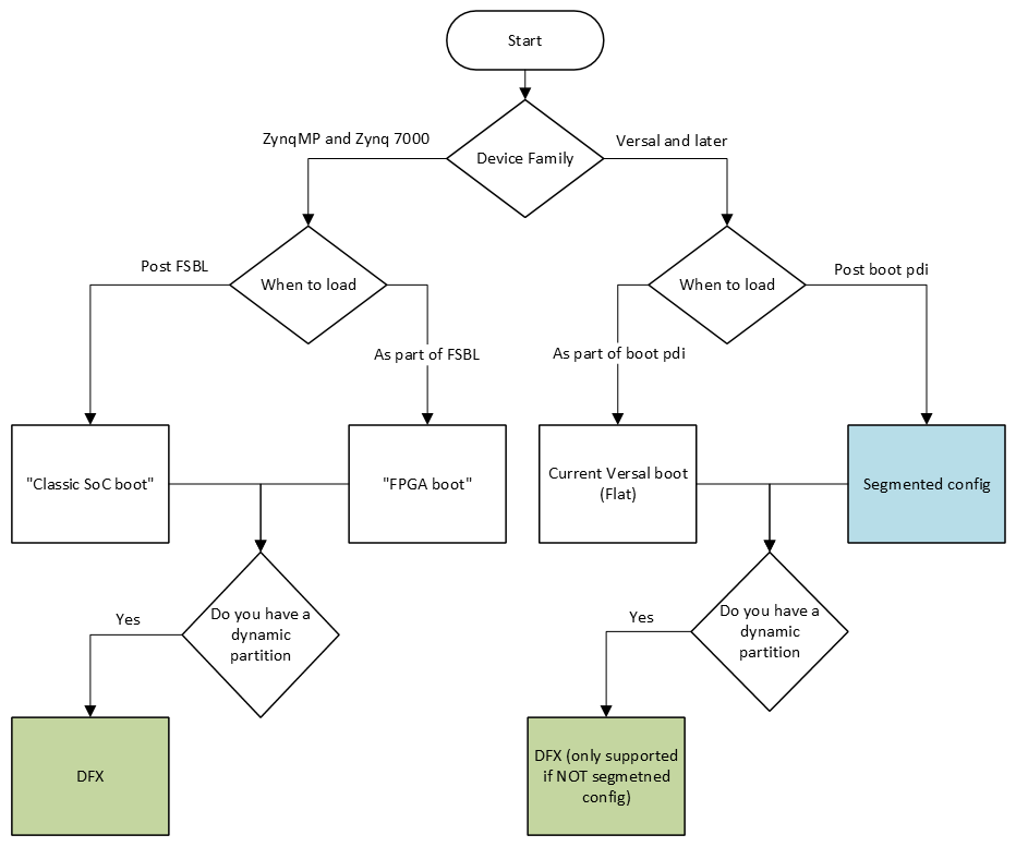
If you are using AMD’s Yocto Project tooling, take a look at the DFX (Green in the below diagram) or Segmented Configuration (Blue in the below diagram) pages.
Definitions
“Module”: A grouping of hardware that can be loaded as a unit, represented by a binary file that represents the machine interpretable hardware (
.binfor AMD Zynq UltraScale+ MPSoC devices, or.pdifor the AMD Versal portfolio), and a hardware description that is interpretable by the software (device tree). Modules are intended to be loaded/enabled/reconfigured at an arbitrary time, by firmware, by bootloaders, by hypervisors, or by individual operating systems.“Segmented configuration”: Only applies to Versal and later devices (although Zynq MPSoC has a similar concept referred to as “classic SoC boot”). “Segmented configuration” is when a subset of the total hardware in the system (usually enough to boot the software), is separate from the rest of the hardware in the system and the software uses special drivers or commands (
fpgamanagerordfxutilin the case of Linux) to load the rest of the hardware.
Steps
Identify hardware that is in the module to be loaded after boot. Hardware design tools can help identify this information, but the system-level design is the primary source of this information.
Isolate the identified hardware to its own device tree file (.dtsi)
AMD has two use cases for reconfiguration: Segmented Configuration and Dynamic Function eXchange (DFX).
For Segmented Configuration, AMD assumes that hardware in the
pl.dtsifile produced by SDTGen correlates 1:1 with the data in the post-boot module.
Modify (using lopper with the appropriate lops) the isolated hardware device tree to ensure it is enclosed in an appropriate block.
The appropriate block is defined by the FPGA driver, the bindings for which are defined here. An example is going from:
/ {
    amba_pl: amba_pl {
        ranges;
        compatible = "simple-bus";
        #address-cells = <2>;
        #size-cells = <2>;
        firmware-name = "zcu_104_demo_mpsoc_preset_wrapper.bit.bin";
        clocking0: clocking0 {
...
to
/dts-v1/;
/plugin/;
&fpga_full{
    firmware-name = "zcu_104_demo_mpsoc_preset_wrapper.bit.bin";
};
&amba{
    clocking0: clocking0 {
...
Remove the isolated hardware from the system device tree. In AMD software flows this is accomplished by removing
pl.dtsifromsystem-top.dtsi.Old version:
/dts-v1/;
#include "zynqmp.dtsi"
#include "zynqmp-clk-ccf.dtsi"
#include "pl.dtsi"
#include "pcw.dtsi"
/ {
    board = "zcu104";
    device_id = "xczu7ev";
    slrcount = <1>;
New version:
/dts-v1/;
#include "zynqmp.dtsi"
#include "zynqmp-clk-ccf.dtsi"
#include "pcw.dtsi"
/ {
    board = "zcu104";
    device_id = "xczu7ev";
    slrcount = <1>;
Compile the isolated hardware information into a device tree binary. (using the device tree complier)
Obtain the FPGA binary file (
.binfile for ZynqMP, or.pdifor Versal and later)If you have a
.bitfile (as opposed to a.binfile), use bootgen to remove the headers and sync words as those are not needed byfpgautil
If using DFX (not Segmented Configuration) Create a shell.json
Put the compiled
.dtbfile, the FPGA binary file, andshell.jsononto your filesystem in/lib/firmware/xilinx.Run
dfx-mgrpointing to/lib/firmware/xlinx.