Board Specific Specifications and Information
This page contains specification and architecture information for the AMD Embedded Development Framework (EDF) that is applicable to specific evaluation boards, including pinout, interfaces, and memory map implementation.
Introduction
Evaluation board specific information can be found in the following sections. The information is organized by device/device family, and then by evaluation board using the board name.
VEK385
Boot Firmware and Linux Disk Images
Boot Firmware Images - OSPI VEK385 - Boot Firmware + boot.pdi:
Refer to Common Specifications
Linux Disk Image - Common Disk Image With Support for This Board
Refer to Common Specifications
Boot Flow - Arm System Ready Compatible Boot Flow With UEFI
AMD EDF v26.11 (VEK385) - AMD Vivado Design Suite 2026.2
OSPI Memory Map - 2G Micron Device (VEK280, VEK385)
For the Micron 2b OSPI device memory device MT35XLU02G part used on VEK280, VEK385 evaluation boards. See Common Specifications for more information.
This part has the same erasable and lockable sector size of 128 KB, which defines the minimum footprint for each section within the OSPI memory map. The overall map is described in the table below and is aligned to the 1 Gb for the “fixed” section. It can facilitate user application space for A/B images, and is pre-allocated for 114 MB to accommodate the larger device targets.
Start Address |
Description |
Size (KB) |
Start Sector |
R or R/W |
MTD |
MultiBoot Offset |
|---|---|---|---|---|---|---|
0x0000 0000 |
Image Selector App |
384 |
0 |
R |
0 |
0x0000 |
0x0006 0000 |
Image Selector App - Backup |
384 |
3 |
R |
1 |
0x000C |
0x000C 0000 |
Image Selector - Scratchpad |
128 |
6 |
R |
2 |
|
0x000E 0000 |
Image Recovery App |
20480 |
7 |
R |
3 |
0x001C |
0x014E 0000 |
Image Recovery - Scratchpad |
128 |
167 |
R |
4 |
|
0x0150 0000 |
SystemReady-DT Update Metadata |
128 |
168 |
R/W |
5 |
|
0x0152 0000 |
SystemReady-DT Update Metadata (Backup) |
128 |
169 |
R/W |
6 |
|
0x0154 0000 |
U-Boot Variables |
128 |
170 |
R/W |
7 |
|
0x0156 0000 |
U-Boot Variables (Backup) |
128 |
171 |
R/W |
8 |
|
0x0158 0000 |
Bank “A” Image Space / Directory |
116736 |
172 |
R/W |
9 |
0x02B0 |
0x0878 0000 |
U-Boot Variables - Bank A - Design option |
128 |
1084 |
R/W |
10 |
|
0x087A 0000 |
U-Boot Variables - Bank A (Backup) |
128 |
1085 |
R/W |
11 |
|
0x087C 0000 |
Bank “B” Image Space / Directory |
51200 |
1086 |
R/W |
12 |
0x10F8 |
0x0F9C 0000 |
U-Boot Variables - Bank B - Design option |
128 |
1998 |
R/W |
13 |
|
0x0F9E 0000 |
U-Boot Variables - Bank B (Backup) |
128 |
1999 |
R/W |
14 |
|
0x0FA0 0000 |
User Scratchpad |
6016 |
2000 |
R/W |
15 |
DDR Memory Map - VEK385
The VEK385 Memory Map is based on the AMD EDF System Memory map standard Common Specifications The following table represents the VEK385 specific map, reflecting the number of RPUs and physical memory available in the platform.
Start Addr |
Size (MB) |
Description |
Fixed/Variable |
XMPU |
|---|---|---|---|---|
Low DDR - 2 GB |
||||
0x000 0000 0000 |
16 |
Versal PLM |
Fixed |
Yes - PLM FW |
0x000 0100 0000 |
6 |
TF-A - Transfer list / handoffs |
Fixed |
TBD |
0x000 0160 0000 |
2 |
TF-A - Core runtime memory |
Fixed |
Yes - TF-A FW |
0x000 0180 0000 |
128 |
OP-TEE shared buffers & dynamic TAs |
Fixed |
Yes - Secure OS/Secure Partition |
0x000 0980 0000 |
8 |
RPU Core 0-1 OpenAMP allocations (4 MB / core) |
x2 RPU Cores |
Yes - RPU |
32 |
Free memory |
|||
0x000 0C00 0000 |
320 (400 MB requested) |
RPU+:term:ISP reservation |
x3 ISP |
Yes - RPU |
0x000 2000 0000 |
1536 |
Linux - Low DDR |
LOW_DDR Remainder |
No |
High DDR |
||||
0x008 0000 0000 |
2048 |
ISP frame buffer allocation (DDRMC closest to ISPs) |
Scale # ISPs |
|
Platform dependent |
Linux - High DDR |
HIGH_DDR Remainder |
||
Platform dependent |
PL & AIE dedicated allocations |
Programing/flashing the OSPI (Primary Boot Device)
See
Programing the UFS / SD Card(Secondary Boot device)
Both VEK385 revisions use a UFS device as the secondary boot
device. The board carries no SD card slot the adaptive SoC can
boot from on either revision, and both multidomain machines deploy a
wic.ufs disk image for it.
For other Versal boards (for example, VEK280 and VCK190), use an SD card as the secondary boot device.
For step-by-step procedures for writing the disk image to either media, see:
VEK385 Basic Board Interfaces
The following picture shows the location of the basic board interfaces. For more information, see the Evaluation board user guide.
The basic board setup is as follows:
Connect the external power supply to the “Power Connector” (J28)
Connect the USB-Type C connector (J26) labeled “USB Type-C JTAG/UART” to the host PC
Connect the RJ45 (J52) labeled “PS Ethernet” to the local network
Connect the RJ45 (J64) labeled “SC Ethernet” (System Controller) to the local network
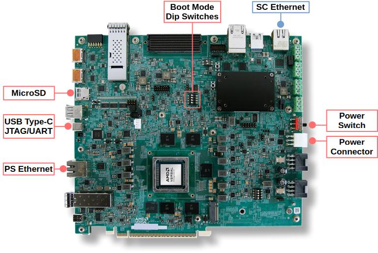
VEK385 board with key interfaces annotated.
VEK385 Powering the Board
To power up the board, connect the board external power supply to an outlet, plug in the external supply to the VEK385 board and turn the board on with the power switch:

VEK385 Power Switch and Power Connector.
VEK385 Default DIP Switch Settings - Boot

System Controller Firmware Update
See the System Controller Wiki for more information https://xilinx-wiki.atlassian.net/wiki/x/AYCGhw
VEK385 UART connections - FTDI-USB
The VEK385 has four serial / UART interfaces. When the FTDI-USB cable is plugged into the VEK385 board it creates four device nodes on the host PC.
The four UART are mapped as follows,
Rev B:
FDTI |
DUT (2VE3858) |
|
|---|---|---|
ADBUS (Device 0) |
||
BDBUS (Device 1) |
PS-UART0 |
PS-UART1 |
NC |
||
PS-UART0 |
||
PS-UART1 |
NC |
Rev A:
FDTI |
DUT (2VE3858) |
|
|---|---|---|
ADBUS (Device 0) |
||
BDBUS (Device 1) |
PS-UART0 |
PS-UART1 |
NC |
PS-UART0 |
|
PS-UART1 |
NC |
FTDI - System Controller - Versal; UART diagram Rev B
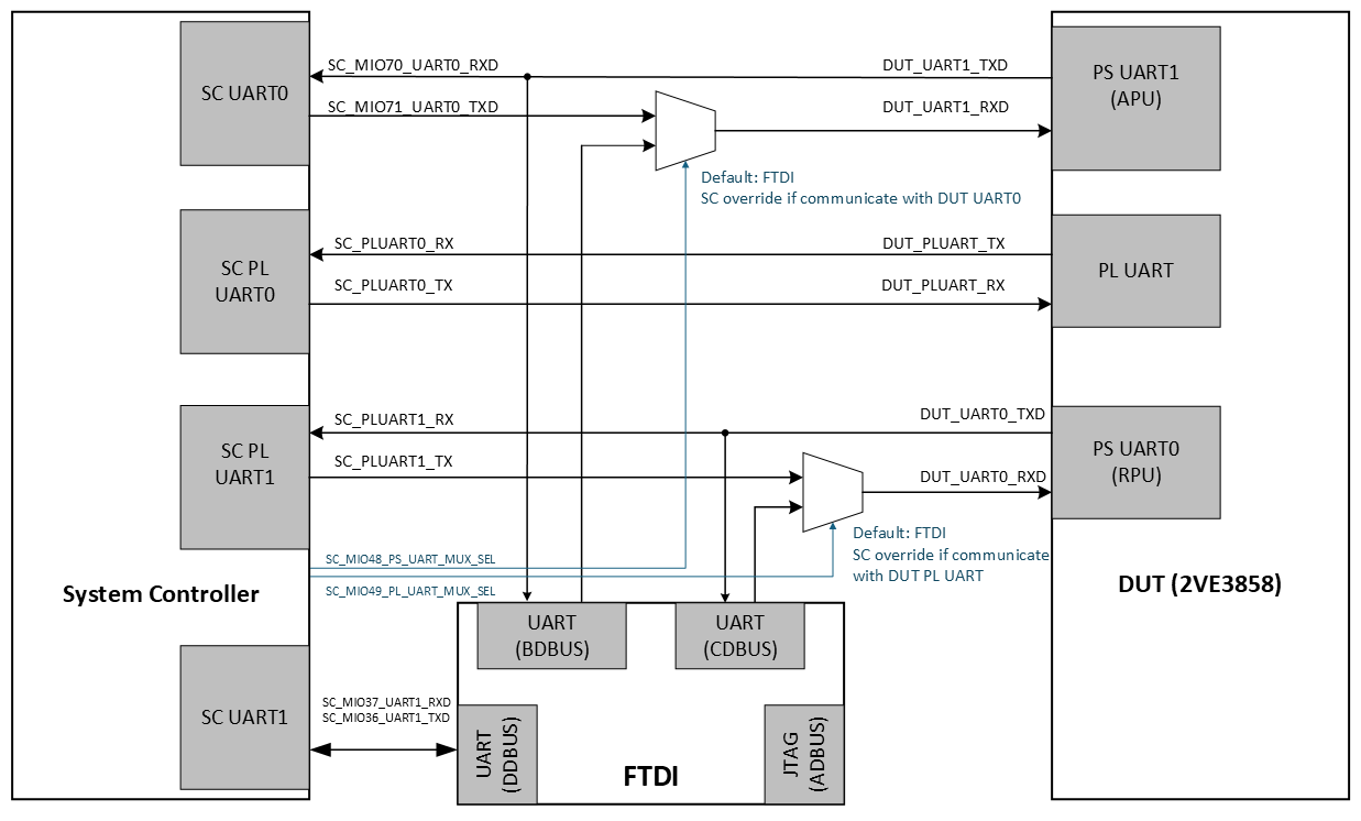
VEK385 Rev B FTDI / System Controller / Versal UART routing.
Rev A

VEK385 Rev A FTDI / System Controller / Versal UART routing.
Versal PS-UART1 is used by the primary user software (U-Boot and Linux). This can be directly accessed by the host PC through the FTDI UART.
Versal PS-UART0 is used by default for auxiliary software (PLM, ASU, RPU) and on Rev A boards is routed to the System Controller for remote UART functionality. In Rev B of the VEK385, PS-UART0 is directly accessible through the FTDI-USB interface. It is a known limitation in this configuration that PLM power-on messages are not accessible in this VEK385 Rev A configuration. The users can work around this by issuing a Versal POR_B and capturing logs from the System Controller.
VEK385 Base Vivado Design for BSPs and PS specifications
This specification inherits from the common and device specific specifications, but also has evaluation board specific items. See also the following:
The Versal Gen 2 AI Edge Series Gen 2 Embedded Common Platform CED from AMD Vivado Design Suite 2026.2 is the base Vivado design used for EDF BSPs.
it is the recommended starting point for Vivado designs to maintain compatibility with the prebuilt OSPI boot images, and EDF prebuilt disk images.
VEK385 PL Board I/O
The Base CED PL design includes AXI-GPIO controllers that must be used of the “GPIO” physical interfaces for customer test. These are summarized in the following table. They are split across unique controllers to align with mapping to Vivado Board File signal groups and to minimize customer confusion on bitwise definitions.
Controller |
Description |
Location |
PL IP Direction |
|---|---|---|---|
PL_AXI_GPIO_0 |
GPIO_LED[3:0] |
Bank 705 & 706 |
Output |
PL_AXI_GPIO_1 |
GPIO_PB[1:0] |
Bank 705 & 706 |
Input |
PL_AXI_GPIO_2 |
GPIO_DIP[3:0] |
Bank 705 & 706 |
Input |
VEK385 MMI Configuration
The MMI configuration for VEK385 is aligned with the VEK385 hardware design. This includes the following configurations:
Base Configuration
PCIe 10GbE HSDP GT = PCIe0 x2 10GbE
USB DisplayPort GT = DP X2 + USB
USB Configuration
USB3.2 = Enabled
USB2.0 = Enabled (automatic with 3.2 enable)
10GbE Configuration
Data Rate = 10G
MDIO = Not enabled / None
External FIFO = Not enabled
External TSU Interface = Not enabled
PTP Interface = Not enabled
DPDC Configuration
Operating Mode = DC Functional
Presentation Mode = Non Live
Video Interface Mode = Native
DP Hot Plug Detect = PMC MIO 48
MMI PCIe Controller 0
Link
Port Type = Root Port of PCIe Root Port Complex
Link Speed = 32 GT/s
Mode = TBD
PERST = None (Handled by SW)
PF Basic, PF BARs, SRIOV - N/A as in Root Port mode
VEK385 MMI Clocks:
Video Clocks - Derived off a common MBUFGCE
MMI 2x Clk = 600 MHz
MMI 1x Clk = 300 MHz
Audio Clock
192kHz x 512 = 98.304 MHz
Dynamic Config = Must be enabled so the DP driver can adjust frequencies based on display resolution.
VEK385 Reference PL Payload Information
See the Discovery and Evaluation
ZCU104
Default Boot Flow
The default boot flow for the EDF Linux BSP for ZCU104 is Common Specifications
See Common Specifications for more information.
ZCU104 Boot Firmware and Linux Disk Images
Boot Firmware Images - QSPI ZCU104 - Boot Firmware + boot.bin:
Refer to Common Specifications
Linux Disk Image - Common Disk Image With Support for This Board
edf-platform-disk-image-amd-cortexa53-mali-common+zynqmp-zcu104-multidomain.rootfs.wic.xz
ZCU104 Multidomain Flash and SD Boot
The zynqmp-zcu104-multidomain machine uses multistage boot with
QSPI flash for boot firmware storage and SD for Linux disk image
content.
Support for this multidomain QSPI + SD flow starts in EDF v26.11 and
later, and uses edf-qspi as the supported boot firmware image recipe.
It inherits from zynqmp-zcu104-sdt-full.yaml and applies a multidomain
overlay set with OpenAMP and libmetal domains.
Flash Memory Map (Multidomain)
The ZCU104 multidomain machine uses the edf-qspi recipe with the 64 MB
QSPI flash. Boot firmware slot A/B offsets follow
SPI_BOOTBIN_OFFSET = 0x15C_0000 0x260_0000.
Start Address |
Description |
Size |
Source |
Purpose |
|---|---|---|---|---|
0x0000_0000 |
Image selector, primary |
384 KB |
|
Initial boot selection |
0x0006_0000 |
Image selector, backup |
384 KB |
|
Backup boot selection |
0x000C_0000 |
Image selector scratch |
128 KB |
Empty |
Reserved scratch space |
0x000E_0000 |
Image recovery |
20 MB |
|
Recovery boot image |
0x014E_0000 |
Image recovery scratch |
128 KB |
Empty |
Reserved scratch space |
0x0150_0000 |
Update metadata, primary |
128 KB |
|
Primary firmware update metadata |
0x0152_0000 |
Update metadata, backup |
128 KB |
|
Backup firmware update metadata |
0x0154_0000 |
U-Boot environment, primary |
128 KB |
Empty |
Reserved environment space |
0x0156_0000 |
U-Boot environment, backup |
128 KB |
Empty |
Reserved environment space |
0x0158_0000 |
Reserved / unallocated |
256 KB |
Empty |
Reserved space |
0x015C_0000 |
|
16.25 MB |
|
Primary boot firmware image |
0x0260_0000 |
|
16.25 MB |
|
Backup boot firmware image |
0x0364_0000 |
User scratch |
9.69 MB |
Empty |
Reserved user scratch space |
0x03FF_0000 |
Manifest |
64 KB |
Manifest generated by |
QSPI image manifest |
Additional Multidomain Post Settings
conf/enable-xilinx-imgrcvry.confis included when available.CFLAGS:append:pn-image-selector = -DXIS_QSPI_FLSHenables QSPI flash support in image-selector.BOOTBIN_INC = libmetal-demo-rpu1.incenables the libmetal demo boot artifact.QEMU_FLASH_TYPE = qspiselects QSPI in QEMU runs.SPI_IMAGE_SIZE = 0x400_0000configures a 64 MB QSPI layout.PREBOOT_CFG_FILE = file://preboot_cmd_zynqmp_multidomain.cfgselects the multidomain preboot script.
Advanced Embedded Software Configurations Included
Xen Dom0 (through
edf-platform-disk-image; see image-variant comparison)OpenAMP runtime packages (through
edf-platform-disk-image); per-board firmware example tarballs to follow in EDF 26.1.1xen-zephyr-domu-imageZephyr DomU payload to follow in EDF 26.2
ZCU104 UART connections - FTDI-USB
The ZCU104 board uses the quad USB-UART chip, that enables four UART interfaces through a single micro-AB USB connector:
ZCU104 Ethernet connections
The ZCU104 board physically uses GEM3 for its Ethernet interface.
ZCU104 base design (CED) and PS specifications
The AMD Vivado design suite project used for the ZCU104 EDF BSP inherits the aims of the common specifications in EDF. The design is created using board automation within Vivado, with additional Tcl scripting. However, there is minimal direct inheritance from the documented common specifications which are AMD Versal device portfolio based.
Refer to the board specific configurations here, which are migrated to Device Specific Specifications as and when additional boards are added.
The AMD Vivado design suite projects used for the ZCU104 EDF BSP are:
zcu104_basewhich can be downloaded from zcu104_basezcu104_pl_vcu_extensiblewhich can be downloaded from zcu104_pl_vcu_extensible
A picture of the block design generated including PL content is shown below:

PL Payload:
Default Payload: - VCU Extensible Platform
AXI-V_FRMBUF_WR
Transfers video pixel data into memory.
AXI-VCU
Encodes and decodes video streams.
AXI-VCU_DDR4_CONTROLLER
Interfaces with DDR4 memory for high-speed video data access.
Additional Payloads:
PS Specifications:
The following default PS configuration is implemented in the embedded common platform CED for Zynq Ultrascale+, and is aligned with common specifications, there are also some board defined items such as fixed MIO, clocks, and enabling clock frequencies enabled by the speed grade of the target device.
PS Peripheral mappings in the CED
CAN1: Mapped to MIO pins 24 and 25.
DisplayPort AUX Channel: Mapped to MIO pins 27 to 30.
ENET3 MDIO: Mapped to MIO pins 76 and 77.
ENET3 data and control signals: Mapped to MIO pins 64 to 75.
GPIO: Assigned to EMIO interface with 92 signals.
I2C1: Mapped to MIO pins 16 and 17.
SD1: Mapped to MIO pins 46 to 51.
TTC0, TTC1, TTC2, TTC3: Assigned to EMIO interface.
UART0: Mapped to MIO pins 18 and 19.
UART1: Mapped to MIO pins 20 and 21.
Interrupts
PS-PL Interrupts
The embedded common platform CED enables two LPD interrupts.
The following table outlines the planned application mapping and utilization of the PS-PL interrupts.
Domain |
IRQ |
Enabled |
Allocation |
|---|---|---|---|
1 |
Yes |
PL Interrupts |
|
9 |
Yes |
PL Interrupts |
IPI Mappings
The embedded common platform CED enables a superset of IPI mappings to support current and future TRDs and are defined in the following table.
These do not impact the PS/PL boundary so are not controlled relative to TRD specific PL designs.
IPI / IRQ |
Enabled |
Master |
Description |
|---|---|---|---|
axi_intc_0 |
Yes |
zynq_ultra_ps_e_0 |
AXI Interrupt Controller (aggregates PL interrupts) |
pl_ps_irq0 |
Yes |
zynq_ultra_ps_e_0 |
|
pl_ps_irq1 |
Yes |
zynq_ultra_ps_e_0 |
DDR Memory Map
The following represents the map reflecting the number of RPUs and physical memory available in the platform.
Region Name |
Start Address |
Size (Bytes) |
Description |
|---|---|---|---|
Main DDR Region |
0x00000000 |
0x80000000 (2 GB) |
Primary DDR accessed through HPx ports (APU/Linux) |
VCU Decode Buffer |
0x4800000000 |
0x80000000 (2 GB) |
VCU decode data through S_AXI_PORT0 |
VCU Encode Buffer |
0x4800000000 |
0x80000000 (2 GB) |
VCU encode data through S_AXI_PORT1 |
VCU Code/Data Region |
0x4800000000 |
0x80000000 (2 GB) |
VCU code buffer through S_AXI_PORT2 |
Framebuffer Read Region |
0x4800000000 |
0x80000000 (2 GB) |
Framebuffer read through S_AXI_PORT4 |
VCU Frame Buffer |
0x4800000000 |
0x80000000 (2 GB) |
VCU frame buffer through S_AXI_PORT3 |
System Level Memory Map
The system level memory map shown here focuses on the DDR, OCM, and TCM allocations within the AMD EDF architecture.
The following table defines the default allocations used by AMD EDF, and what AMD reference designs use as their starting points. Due to the nature of device tree definition, end users can change this.
Start Address |
Description |
|---|---|
0x80000000 |
|
0xA0000000 |
Framebuffer Control Read/Write |
0xA0010000 |
VCU S_AXI_LITE |
0x4800000000 |
DDR Controller S_AXI_PORT3 |
0x4800000000 |
DDR Controller S_AXI_PORT4 |
0xC0000000 |
QSPI Linear (HPx_QSPI) |
0xFF000000 |
HPx_LPS_OCM |
0x00000000 |
HPx_DDR_LOW (Main DDR) |
0x4800000000 |
VCU Code/Data/Enc/Dec Buffers |
ZCU111

The AMD ZCU111 evaluation board.
Default Boot Flow
The default boot flow for the EDF Linux BSP for ZCU111 is Common Specifications
See Common Specifications for more information.
ZCU111 Boot Firmware and Linux Disk Images
Boot Firmware Images
Not applicable
Linux Disk Image - Common Disk Image With Support for This Board
edf-platform-disk-image-amd-cortexa53-common+zynqmp-zcu111-multidomain.rootfs.wic.xz
Advanced Embedded Software Configurations Included
Xen Dom0 (through
edf-platform-disk-image; see image-variant comparison)OpenAMP runtime packages (through
edf-platform-disk-image); per-board firmware example tarballs to follow in EDF 26.1.1xen-zephyr-domu-imageZephyr DomU payload to follow in EDF 26.2
ZCU111 UART connections - FTDI-USB
The ZCU111 board uses the quad USB-UART chip, that enables four UART interfaces through a single micro-AB USB connector:
ZCU111 Ethernet connections
While the ZCU111 board physically uses GEM3 for its Ethernet interface.
ZCU111 base design (CED) and PS specifications
The AMD Vivado design suite project used for the ZCU111 EDF BSP
is: zcu111_base which can be downloaded from
zcu111_base
A picture of the block design generated including PL content is shown below:
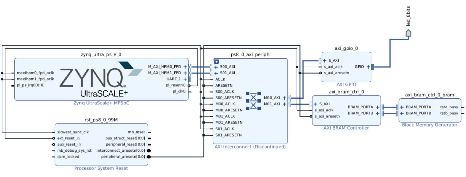
ZCU111 base block design.
PL Payload - EDF minimal PL Payload
PL Payload Content
Additional Payloads
EDF v26.11 - None
PS Specifications
The following default PS configuration is implemented in the embedded common platform CED for Zynq UltraScale+, and is aligned with common specifications, there are also some board defined items such as fixed MIO, clocks, and enabling clock frequencies enabled by the speed grade of the target device.
PS Peripheral mappings in the CED
MIO Controller — All MIO controllers (for example, UART, I2C, SPI) associated with fixed PS peripherals are enabled and configured based on the board design.
MIO I/O Configuration — MIO pins are configured based on the platform hardware setup, including drive strength, slew rate, and pull-up/down settings.
UART1 — Enabled for console communication; mapped through MIO pins to provide serial access during boot and runtime.
AXI HP Interfaces (HPM0_FPD, HPM1_FPD) — Configured so the PS can access PL-connected peripherals like BRAM, GPIO, and Interconnect through high-performance AXI master ports.
Interrupts
IPI Mappings
The embedded common platform CED enables a superset of IPI mappings to support current and future TRDs and are defined in the following table.
These do not impact the PS/PL boundary so are not controlled relative to TRD specific PL designs.
IPI |
Enabled |
Master |
Description |
|---|---|---|---|
IPI 0 |
Yes |
Inter-core messaging (for example, APU0 ↔ PMU) |
|
IPI 1 |
Yes |
RPU0 |
Real-time processor messaging |
IPI 2 |
Yes |
RPU1 |
Real-time processor messaging |
IPI 3 |
Yes |
||
Yes |
Platform management functions |
||
Yes |
Platform management functions (bufferless) |
||
Yes |
Security management functions |
DDR Memory Map
The following represents the map reflecting the number of RPUs and physical memory available in the platform.
Start Address |
End Address |
Size (MB) |
Description |
|---|---|---|---|
0x00000000 |
0x3ECFFFFF |
~1003 |
Usable DDR (Linux, apps, heap) |
0x3ED00000 |
0x3EDFFFFF |
1 |
Reserved for RPU / OpenAMP |
0x3EE00000 |
0x3FFFFFFF |
~19 |
Usable DDR continues |
0xFD070000 |
0xFD09FFFF |
0.1875 (~192 KB) |
DDR Controller (registers only) |
System Level Memory Map
The system level memory map shown here focuses on the DDR, OCM, and TCM allocations within the AMD EDF architecture.
The following table defines the default allocations used by AMD EDF, and what AMD reference designs use as their starting points. Due to the nature of device tree definition, end users can change this.
Start Address |
Description |
|---|---|
0x00000000 |
DDR Memory |
0x3ED00000 |
Reserved (RPU/OpenAMP) |
0xFD070000 |
DDR Controller Regs |
0xFD080000 |
DDR PHY |
0xFD090000 |
DDR QoS Controller |
0xFD000000 |
XMPU DDR Protection |
0xFFA70000 |
OCM XMPU Config |
0xA0010000 |
AXI BRAM (PL) |
0xFFE00000 |
R5 TCM (global) |
0xFFEB0000 |
R5_1 BTCM Global |
0xFFE20000 |
R5_0 BTCM Global |
0xFFE00000 |
R5_0 ATCM Global |
ZCU216

The AMD ZCU216 evaluation board.
Default Boot Flow
The default boot flow for the EDF Linux BSP for ZCU216 follows the single-stage boot described in Common Specifications.
ZCU216 Boot Firmware and Linux Disk Images
Boot Firmware Images
Not applicable
Linux Disk Image - Common Disk Image With Support for This Board
edf-platform-disk-image-amd-cortexa53-common+zynqmp-zcu216-multidomain.rootfs.wic.xz
Advanced Embedded Software Configurations Included
Xen Dom0 (through
edf-platform-disk-image; see image-variant comparison)OpenAMP runtime packages (through
edf-platform-disk-image); per-board firmware example tarballs to follow in a future EDF releasexen-zephyr-domu-imageZephyr DomU payload to follow in a future EDF release
ZCU216 UART connections - FTDI-USB
The ZCU216 board uses the quad USB-UART chip, that enables four UART interfaces through a single micro-AB USB connector:
ZCU216 Ethernet connections
The ZCU216 board uses GEM3, mapped to MIO 64 to 75 through RGMII.
ZCU216 base design (CED) and PS specifications
The AMD Vivado design suite project used for the ZCU216 EDF BSP
is: zcu216_base which can be downloaded from
zcu216_base
ZCU216 uses the same Zynq UltraScale+ embedded common platform CED as the other Zynq RFSoC boards. The PL payload, PS specifications, IPI mappings, DDR memory map, and system level memory map are shared with ZCU111; refer to that section for the detailed tables.
VEK280
OSPI Memory Map - VEK280
For the Micron 2b OSPI device memory device MT35XLU02G part used on VEK280, VEK385 evaluation boards. See Common Specifications for more information.
VCK190
Boot Firmware Images - QSPI VCK190 - Boot Firmware + boot.bin:
Refer to Common Specifications
VCK190 QSPI Memory Map
The VCK190 multidomain machine uses the edf-qspi recipe with the 256 MB
QSPI flash on the XBM daughter card.
Start Address |
Description |
Size |
Source |
Purpose |
|---|---|---|---|---|
0x0000_0000 |
Image selector, primary |
384 KB |
|
Initial boot selection |
0x0006_0000 |
Image selector, backup |
384 KB |
|
Backup boot selection |
0x000C_0000 |
Image selector scratch |
128 KB |
Empty |
Reserved scratch space |
0x000E_0000 |
Image recovery |
20 MB |
|
Recovery boot image |
0x014E_0000 |
Image recovery scratch |
128 KB |
Empty |
Reserved scratch space |
0x0150_0000 |
Update metadata, primary |
128 KB |
|
Primary firmware update metadata |
0x0152_0000 |
Update metadata, backup |
128 KB |
|
Backup firmware update metadata |
0x0154_0000 |
U-Boot environment, primary |
128 KB |
Empty |
Reserved environment space |
0x0156_0000 |
U-Boot environment, backup |
128 KB |
Empty |
Reserved environment space |
0x0158_0000 |
Reserved / unallocated |
256 KB |
Empty |
Reserved space |
0x015C_0000 |
|
114.25 MB |
|
Primary boot firmware image |
0x0880_0000 |
|
114.25 MB |
|
Backup boot firmware image |
0x0FA4_0000 |
User scratch |
5.69 MB |
Empty |
Reserved user scratch space |
0x0FFF_0000 |
Manifest |
64 KB |
Manifest generated by |
QSPI image manifest |
VEK280 and VCK190 - Common Specifications

The AMD VEK280 evaluation board.

The AMD VCK190 evaluation board.
Boot Firmware and Linux Disk Images
Linux Disk Image - Common Disk Image With Support for This Board
Refer to Common Specifications. For the SD card partition layout used as the secondary boot device, see EDF Disk Image Layout. See the System Controller Wiki for more information https://xilinx-wiki.atlassian.net/wiki/x/AYCGhw
UART connections - FTDI-USB - VEK280, VCK190
Ethernet connections
VEK280
The VEK280 board physically uses GEM0 for its Ethernet interface.
GEM0 is mapped to PS MIO[48] and PS LPD MIO[0:11, 24:25], which corresponds to a standard mapping for RGMII through RJ-45.
VCK190
The VCK190 board physically uses dual GEM0/1 for its Ethernet interface.
GEM0/1 is mapped to PS MIO[48:49] and PS LPD MIO[0:25], which corresponds to a standard mapping for RGMII through RJ-45.
Base design (CED) and PS specifications
VEK280
The AMD Vivado design suite project used for the VEK280 EDF BSP is:
vek280_basewhich can be downloaded from vek280_base
VCK190
The AMD Vivado design suite project used for the VCK190 EDF BSP are:
vck190_basewhich can be downloaded from vck190_base
A picture of the block design generated including PL content is shown below:
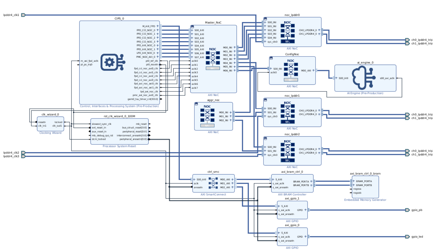
VCK190 base block design.
PL Payload:
PS Specifications:
The following default PS configuration is implemented in the embedded common platform CED for Zynq Ultrascale+, and is aligned with common specifications, there are also some board defined items such as fixed MIO, clocks, and enabling clock frequencies enabled by the speed grade of the target device.
PS Peripheral mappings in the CED
AXI BRAM Controller: Mapped to the address range for Block RAM access.
AXI GPIO (gpio_0): Mapped to EMIO interface with 256 GPIO signals.
AXI GPIO (gpio_1): Mapped to EMIO interface with 256 additional GPIO signals.
AI Engine: Mapped to a configurable address space for AI processing.
Master NoC: Mapped to system’s AXI address space for interconnectivity.
AXI NoCs: Mapped to address range facilitating access between different IP blocks.
Clocking Wizard: Mapped to the address space for clock signal management.
Timers: Mapped to EMIO interface with event generation capabilities.
DDR Memory Interfaces: Mapped to the address space connecting LPDDR4 memory.
I2C (0): Mapped to MIO pins for connecting to external devices (specific pins per design).
UART (Serial Communication): Mapped to MIO pins for serial data transfer (specific pins per design).
SPI (Serial Peripheral Interface): Mapped to MIO pins for SPI connections (specific pins per design).
Interrupts
PS-PL Interrupts
The embedded common platform CED enables one LPD interrupt.
The following table outlines the planned application mapping and utilization of the PS-PL interrupts.
Domain |
IRQ |
Enabled |
Allocation |
|---|---|---|---|
0 |
Yes |
PL Interrupts |
IPI Mappings
The embedded common platform CED enables a superset of IPI mappings to support current and future TRDs and are defined in the following table.
These do not impact the PS/PL boundary so are not controlled relative to TRD specific PL designs.
IPI / IRQ |
Enabled |
Master |
Description |
|---|---|---|---|
Yes |
|||
Yes |
|||
Yes |
IPI used by PSM (Platform Service Manager) for event signaling. |
||
IPI 0 |
Yes |
A72 |
|
IPI 1 |
Yes |
R5 0 |
Used by RPU core 0 for inter-core communication. |
IPI 2 |
Yes |
R5 1 |
Used by RPU core 1 for inter-core communication. |
IPI 3 |
Yes |
A72 |
|
IPI 4 |
Yes |
A72 |
|
IPI 5 |
Yes |
A72 |
|
IPI 6 |
Yes |
A72 |
DDR Memory Map
The following represents the map reflecting the number of RPUs and physical memory available in the platform.
Region Name |
Start Address |
Size (Bytes) |
Description |
|---|---|---|---|
C0_DDR_LOW0 |
0x0000_0000 |
2 GB |
DDR region on Controller 0, Channel 0 |
C0_DDR_LOW1 |
0x8000_0000 |
2 GB |
DDR region on Controller 0, Channel 1 |
C1_DDR_CH1 |
0x5000_0000_0000 |
4 GB |
DDR region on Controller 1, Channel 1 |
C1_DDR_CH2 |
0x6000_0000_0000 |
4 GB |
DDR region on Controller 1, Channel 2 |
C2_DDR_LOW0 |
0x0000_0000 |
2 GB |
DDR region on Controller 2, Channel 0 |
C2_DDR_LOW1 |
0x8000_0000 |
2 GB |
DDR region on Controller 2, Channel 1 |
C3_DDR_LOW0 |
0x0000_0000 |
2 GB |
DDR region on Controller 3, Channel 0 |
C3_DDR_LOW1 |
0x8000_0000 |
2 GB |
DDR region on Controller 3, Channel 1 |
C1_DDR_LOW0 |
0x0000_0000 |
2 GB |
DDR region on Controller 1, Channel 0 (LPD NOC) |
C1_DDR_LOW1 |
0x8000_0000 |
2 GB |
DDR region on Controller 1, Channel 1 (LPD NOC) |
System Level Memory Map
Start Address |
Description |
|---|---|
0x0000_0000 |
DDR C0 LOW0 |
0x8000_0000 |
DDR C0 LOW1 |
0xA400_0000 |
AXI BRAM Controller |
0xA600_0000 |
AXI GPIO 0 |
0xA601_0000 |
AXI GPIO 1 |
0x2000_0000_0000 |
AI Engine Memory Space |
0x5000_0000_0000 |
DDR C1 CH1 |
0x6000_0000_0000 |
DDR C1 CH2 |
0xFFFC_0000 |
OCM |
VRK160

The AMD VRK160 evaluation board.
Note
The versal-vrk160-revb-sdt-seg and versal-vrk160-revb-multidomain
machines (VRK160 Rev B) use the same board hardware specifications
documented in this section.
Boot Firmware and Linux Disk Images
Boot Firmware Images - OSPI VRK160 - Boot Firmware + boot.pdi:
Refer to Common Specifications
Linux Disk Image - Common Disk Image With Support for This Board
Refer to Common Specifications
VRK160 OSPI Memory Map
OSPI Device Specifications:
Device: Micron 2Gbit Octal SPI Flash Memory (MT35XU02GCBA1G12-0SIT)
Capacity: 256 MB (2Gbit)
Configuration: 24-ball T-PBGA, 05/6 mm x 8 mm (5x5 array)
Interface: OSPI with PS_MODE[3:0] set to “1000”
Operating Temperature: –40°C to 85°C
Clock Frequency: Maximum 200 MHz in DDR mode
Memory Map Table:
Start Address |
Description |
Size (MB) |
Size (KB) |
Start Sector |
R or R/W |
MTD |
MultiBoot Offset |
|---|---|---|---|---|---|---|---|
0x0000_0000 |
Boot Header/Image Selector |
1 |
1024 |
0 |
R |
mtd0 |
0x0000 |
0x0010_0000 |
PLM (Platform Loader Manager) |
2 |
2048 |
16 |
R |
mtd1 |
|
0x0030_0000 |
1 |
1024 |
48 |
R |
mtd2 |
||
0x0040_0000 |
4 |
4096 |
64 |
R |
mtd3 |
||
0x0080_0000 |
Linux Kernel Image |
32 |
32768 |
128 |
R |
mtd4 |
|
0x0280_0000 |
Device Tree Blob |
1 |
1024 |
640 |
R |
mtd5 |
|
0x0290_0000 |
Root Filesystem |
128 |
131072 |
656 |
R |
mtd6 |
|
0x0A90_0000 |
User Data/Configuration |
32 |
32768 |
2704 |
R/W |
mtd7 |
|
0x0C90_0000 |
Recovery/Golden Image |
32 |
32768 |
3216 |
R |
mtd8 |
0x0C90_0000 |
0x0E90_0000 |
Bitstream Storage |
24 |
24576 |
3728 |
R/W |
mtd9 |
|
0x1010_0000 |
Reserved |
16 |
16384 |
4112 |
VRK160 DDR Memory Map
Start Addr |
Size (MB) |
Description |
Fixed/Variable |
XMPU |
|---|---|---|---|---|
0x0000_0000 |
2048 |
DDR_CH0_LEGACY - Low Memory Region |
Fixed |
XMPU0 |
0x8000_0000 |
0 |
Reserved |
||
0x0008_0000_0000 |
2048 |
DDR_CH0_MED - Extended Memory Region |
Fixed |
XMPU1 |
0x0500_0000_0000 |
4096 |
DDR_CH1 - Channel 1 Memory |
Fixed |
XMPU2 |
0x0600_0000_0000 |
4096 |
DDR_CH2 - Channel 2 Memory |
Fixed |
XMPU3 |
0x0700_0000_0000 |
4096 |
DDR_CH3 - Channel 3 Memory |
Fixed |
XMPU4 |
VRK160 Programing/flashing the OSPI (Primary Boot Device)
See
VRK160 Programing the SD Card / UFS (Secondary Boot device)
VRK160 Basic Board Interfaces
The following describes the location of the basic board interfaces.
Basic Board Setup:
Connect the external power supply to the “Power Input” connector
12 V DC power input
Connected to the Digital Power Supplies module
Connect the USB cable to the “FTDI USB” interface to the host PC
Connect the RJ45 connector to the local network
Connected through the K24 System Controller
Provides network connectivity for system management
Connect the SD Card to the “uSD 3.0” slot
MicroSD card slot for secondary boot and storage
Supports up to UHS-I speeds
VRK160 Powering the Board
To power up the board, connect the board external power supply to an outlet, plug in the external supply to the VRK160 board and turn the board on with the power switch.
Configuration Modes (MODE[3:0])
The VRK160 uses a 4-position DIP switch with pulldown resistors to
configure the boot mode. The MODE[3:0] pins are connected to the Versal
device through the System Controller. The System Controller
PS MIO pins are connected to MODE[3:0], allowing isolation
through open-drain buffers for reading the user-selected boot mode.
DIP Switch Configuration :
Boot Mode |
Mode Pins [3:0] |
DIP Switch Setting |
Interface |
Description |
|---|---|---|---|---|
JTAG |
0000 |
OFF-OFF-OFF-OFF |
JTAG Dedicated IO |
JTAG boot mode for debugging |
OSPI |
1000 |
OFF-OFF-OFF-ON |
PMC_MIO |
Default boot mode - Boot from OSPI flash |
SD1 3.0 |
1110 |
OFF-ON-ON-ON |
PMC_MIO |
Boot from SD card slot |
VRK160 System Controller Firmware Update
See the System Controller Wiki for more information https://xilinx-wiki.atlassian.net/wiki/x/AYCGhw
VRK160 UART connections - FTDI-USB
The VRK160 has four serial / UART interfaces. The four UART are mapped as follows,
System Controller (K24) |
DUT (S71/S72) |
|
|---|---|---|
ADBUS (Device 0) |
||
BDBUS (Device 1) |
SC-UART0 |
PS-UART0 |
CDBUS (Device 2) |
SC-UART1 |
|
DDBUS (Device 3) |
PS-UART1 |
Connection Details:
ADBUS (Device 0):
Direct JTAG connection to S71/S72
Used for programming and debugging
No System Controller involvement
BDBUS (Device 1):
System Controller UART0 monitors PS-UART0
Primary PS console output
Boot messages and Linux console
CDBUS (Device 2):
System Controller UART1 monitors PL-UART
Programmable Logic debug output
User application console from PL
DDBUS (Device 3):
VRK160 Ethernet Connections
Ethernet Interface Overview
The VRK160 board provides Ethernet connectivity through the K24 System Controller, which manages network interfaces for both system management and user applications.
Ethernet Connection Details
Interface |
Connector |
Controller |
Speed |
Purpose |
|---|---|---|---|---|
System Controller Ethernet |
RJ45 |
10/100/1000 Mb/s |
Board management, configuration |
|
PS Ethernet (if available) |
Through K24 |
S71/S72 PS |
10/100/1000 Mb/s |
User applications |
VRK160 Base Vivado Design for BSPs and PS specifications
This specification inherits from the common and device specific specifications but also has evaluation board specific items. See also the following:
VRK160 PL Board I/O
Interface |
Connector/Component |
Type |
Specifications |
PL Bank |
Voltage |
Purpose |
|---|---|---|---|---|---|---|
FMC+ (FMCP GEN I/Os) |
FMCP Connector |
High-Speed I/O |
FMC+ HPC Standard |
Multiple |
1.2 V-3.3 V |
Expansion cards, Custom I/O |
HD I/O |
Board Edge |
Differential I/O |
High-speed differential pairs |
HD I/O Banks |
1.2 V |
High-speed serial protocols |
XSIO (Extended Serial I/O) |
Board Edge |
Serial I/O |
Multi-gigabit transceivers |
GTY Banks |
1.2 V |
Serial protocols, PCIe |
PL UART |
115200,8,N,1 |
HP Bank |
3.3 V |
PL debug console |
||
ADC Interface |
Carlisle Connector |
Analog Input |
High-speed ADC |
Analog |
Data acquisition, DSP |
|
DAC Interface |
Carlisle Connector |
Analog Output |
High-speed DAC |
Analog |
Waveform generation |
|
RF CLK SMA |
SMA Connectors |
Clock I/O |
DC-6 GHz |
Clock-capable |
1.8 V |
RF clock input/output |
Memory CLK SMA |
SMA Connectors |
Clock I/O |
LPDDR5X clocks |
Clock-capable |
1.8 V |
Memory clock probe |
General Purpose SMA |
SMA Connectors |
Flexible I/O |
DC-6 GHz |
HP Banks |
1.8 V |
Test points, triggers |
GPIO Headers |
Pin Headers |
Digital I/O |
User-defined |
HP Banks |
1.8 V/3.3 V |
General purpose I/O |
CSPF56 |
CSPF56 Connector |
Mixed Signal |
56-pin interface |
Multiple |
1.8 V/3.3 V |
Custom expansion |
SYSMON Header |
Pin Header |
Monitor |
Analog monitoring |
Analog |
System monitoring |
|
Board EEPROM |
I2C Device |
Storage |
256 bytes min |
HP Bank |
3.3 V |
Board ID, user data |
VRK160 MMI Configuration
Memory-Mapped Interface (MMI) Overview
The VRK160 provides several MMI configuration options for system monitoring and control.
MMI Components:
SYSMON Header
System monitoring interface
Temperature and voltage monitoring
Connected to Versal System Monitor
Provides real-time telemetry data
General Purpose SMAs
SubMiniature version A connectors
Flexible signal routing
Can be configured for:
Clock inputs/outputs
Trigger signals
Test points
Custom I/O
Memory CLK SMAs
Dedicated SMA connectors for memory clocking
LPDDR5X clock connections:
2x16 interface
1x32 interface (x2)
Enables external clock injection for testing
Supports clock monitoring and measurement
MMI Configuration Options:
Software-configurable through Versal CIPS
Hardware strapping options through DIP switches
Runtime configuration through System Controller
VRK160 MMI Clocks
Clock Architecture Overview
The VRK160 implements a sophisticated clocking scheme to support various interfaces and performance requirements.
Primary Clock Sources:
SI5518 Clock Generator
Reference clock generator
Programmable output frequencies
Low-jitter performance
I2C programmable
Provides system reference clocks
SI95314 Clock Generators (x2)
Two independent clock generator ICs
Multiple output channels
Support for different clock domains
Programmable through I2C interface
RF CLK SMAs
RF clock interfaces through SMA connectors
Support for external clock injection
Clock distribution to RF sections
Enables synchronization with external equipment
VRK160 Reference PL Payload Information
See the Discovery and Evaluation
ZC702

The AMD ZC702 evaluation board.
Default Boot Flow
The default boot flow for the EDF Linux BSP for ZC702 is Common Specifications
See Common Specifications for more information.
ZC702 Boot Firmware and Linux Disk Images
Boot Firmware Images
Not applicable
Linux Disk Image - Common Disk Image With Support for This Board
edf-linux-disk-image-amd-cortexa9thf-neon-common+zynq-zc702-sdt-full.rootfs.wic.xz
Advanced Embedded Software Configurations Included
None
OpenAMP and XEN to follow in a future release
ZC702 UART Interfaces:
USB-to-UART Bridge Overview
The ZC702 board contains a Silicon Labs CP2103GM USB-to-UART bridge device (U36) which allows a connection to a host computer with a USB port. The USB cable is supplied in the ZC702 Evaluation Kit. The CP2103GM is powered by the USB 5 V provided by the host PC when the USB cable is plugged into the USB port on the ZC702 board.
Key Features:
Bridge IC: CP2103GM 1X and 4X pins (Silicon Labs)
Location: U36 on the board
Power: USB 5 V powered from host PC
Drivers: Silicon Labs provides royalty-free Virtual COM Port (VCP) drivers
USB Connector Pin Assignments (J17)
USB Connector (J17) Pin |
Net Name |
Description |
CP2103GM (U36) Pin |
Name |
|---|---|---|---|---|
1 |
VBUS |
USB UART_VBUS |
+5 V VBUS Powered |
7 |
2 |
D_N |
USB UART_D_N |
Bidirectional differential serial data (N side) |
5 |
3 |
D_P |
USB UART_D_P |
Bidirectional differential serial data (P side) |
4 |
5 |
GND |
USB_UART_GND |
Signal ground |
2 |
UART Signal Definitions
The USB Connector pin assignments and signal definitions between J17 and U36 are listed in Table 1-15.
XC7Z020 SoC to CP2103 Connections
XC7Z020 SoC (U1) Bank 500 |
CP2103GM Device (U36) |
|||
|---|---|---|---|---|
Pin Name |
Pin Number |
Function |
Direction |
Net Name |
PS_MIO14 |
D11 |
TX |
O |
USB_UART_RX |
PS_MIO15 |
E14 |
RX |
I |
USB_UART_TX |
ZC702 Ethernet connections
ZC702 base design (CED) and PS specifications
CED Overview
The ZC702 Configurable Example Design (CED) provides a base platform for Zynq-7000 development with pre-configured PS and basic PL infrastructure.
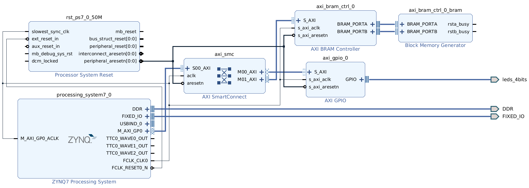
ZC702 Configurable Example Design (CED) base block design.
Base Design Components:
Processing System (PS):
Zynq-7020 (XC7Z020-CLG484)
Dual-core Arm Cortex-A9 @ 667 MHz
DDR3 interface configured
Standard peripheral set enabled
PL Infrastructure:
PS Specifications
Processor Configuration:
Dual Arm Cortex-A9 cores
32 KB L1 I-cache, 32 KB L1 D-cache per core
512 KB shared L2 cache
NEON SIMD extensions
VFPv3 floating point
Memory Interfaces:
DDR3: 1 GB @ 533 MHz (1066MT/s), 32-bit wide
QSPI: 128 Mb flash for boot
OCM: 256 KB on-chip memory
Clock Configuration:
ZC702 Processing System Peripheral Mappings in the Configurable Example Design
Peripheral |
MIO Pins |
Function |
Notes |
|---|---|---|---|
UART1 |
MIO 48-49 |
Console UART |
115200 baud |
USB0 |
MIO 28-39 |
USB 2.0 Host/Device |
ULPI interface |
GEM0 |
MIO 16-27 |
Gigabit Ethernet |
RGMII to PHY |
SD0 |
MIO 40-45 |
SD Card |
4-bit mode |
QSPI |
MIO 1-6 |
Boot Flash |
Single I/O mode |
GPIO |
MIO 0, 7, 8-15, 46-47, 50-51 |
Various |
Buttons, LEDs |
PL Payload
Default Payload - Basic Platform:
Components:
Interrupts
PS Peripheral Interrupt Mappings
IRQ ID |
Interrupt Source |
Description |
|---|---|---|
0-15 |
SGI[0:15] |
Software Generated Interrupts |
27 |
CPU Global Timer |
Arm Cortex-A9 global timer |
29 |
CPU Private Timer |
Arm Cortex-A9 private timer |
30 |
Arm Cortex-A9 private watchdog |
|
32 |
L2 Cache |
L2 cache controller interrupt |
33 |
OCM |
On-chip memory controller |
35 |
PMU0 |
Performance monitor unit CPU0 |
36 |
PMU1 |
Performance monitor unit CPU1 |
37 |
XADC |
System monitor interrupt |
38 |
DevC/PCAP |
Device configuration interrupt |
39 |
SWDT |
System watchdog timer |
40 |
TTC0_0 |
Triple timer counter 0, timer 0 |
41 |
TTC0_1 |
Triple timer counter 0, timer 1 |
42 |
TTC0_2 |
Triple timer counter 0, timer 2 |
43 |
DMAC_Abort |
DMA controller abort |
44 |
DMAC0 |
DMA channel 0 |
45 |
DMAC1 |
DMA channel 1 |
46 |
DMAC2 |
DMA channel 2 |
47 |
DMAC3 |
DMA channel 3 |
48 |
SMC |
Static memory controller |
49 |
QSPI |
Quad-SPI controller |
50 |
GPIO |
GPIO controller |
51 |
USB0 |
USB controller 0 |
52 |
GEM0 |
Gigabit Ethernet MAC 0 |
53 |
GEM0_Wake |
GEM0 wake on LAN |
54 |
SDIO0 |
SD/SDIO controller 0 |
55 |
I2C0 |
I2C controller 0 |
56 |
SPI0 |
SPI controller 0 |
57 |
UART0 |
UART controller 0 |
58 |
CAN0 |
CAN controller 0 |
59 |
FPGA0 |
|
60 |
FPGA1 |
|
61 |
FPGA2 |
|
62 |
FPGA3 |
|
63 |
FPGA4 |
|
64 |
FPGA5 |
|
65 |
FPGA6 |
|
66 |
FPGA7 |
|
67 |
TTC1_0 |
Triple timer counter 1, timer 0 |
68 |
TTC1_1 |
Triple timer counter 1, timer 1 |
69 |
TTC1_2 |
Triple timer counter 1, timer 2 |
70 |
DMAC4 |
DMA channel 4 |
71 |
DMAC5 |
DMA channel 5 |
72 |
DMAC6 |
DMA channel 6 |
73 |
DMAC7 |
DMA channel 7 |
74 |
USB1 |
USB controller 1 |
75 |
GEM1 |
Gigabit Ethernet MAC 1 |
76 |
GEM1_Wake |
GEM1 wake on LAN |
77 |
SDIO1 |
SD/SDIO controller 1 |
78 |
I2C1 |
I2C controller 1 |
79 |
SPI1 |
SPI controller 1 |
80 |
UART1 |
UART controller 1 |
81 |
CAN1 |
CAN controller 1 |
82 |
FPGA8 |
|
83 |
FPGA9 |
|
84 |
FPGA10 |
|
85 |
FPGA11 |
|
86 |
FPGA12 |
|
87 |
FPGA13 |
|
88 |
FPGA14 |
|
89 |
FPGA15 |
|
90 |
Parity |
RAM parity error |
PS-PL Interrupts
Interrupt Signal |
IRQ ID |
Direction |
Description |
|---|---|---|---|
IRQ_F2P[0] |
59 |
Fabric to PS interrupt 0 |
|
IRQ_F2P[1] |
60 |
Fabric to PS interrupt 1 |
|
IRQ_F2P[2] |
61 |
Fabric to PS interrupt 2 |
|
IRQ_F2P[3] |
62 |
Fabric to PS interrupt 3 |
|
IRQ_F2P[4] |
63 |
Fabric to PS interrupt 4 |
|
IRQ_F2P[5] |
64 |
Fabric to PS interrupt 5 |
|
IRQ_F2P[6] |
65 |
Fabric to PS interrupt 6 |
|
IRQ_F2P[7] |
66 |
Fabric to PS interrupt 7 |
|
IRQ_F2P[8] |
82 |
Fabric to PS interrupt 8 |
|
IRQ_F2P[9] |
83 |
Fabric to PS interrupt 9 |
|
IRQ_F2P[10] |
84 |
Fabric to PS interrupt 10 |
|
IRQ_F2P[11] |
85 |
Fabric to PS interrupt 11 |
|
IRQ_F2P[12] |
86 |
Fabric to PS interrupt 12 |
|
IRQ_F2P[13] |
87 |
Fabric to PS interrupt 13 |
|
IRQ_F2P[14] |
88 |
Fabric to PS interrupt 14 |
|
IRQ_F2P[15] |
89 |
Fabric to PS interrupt 15 |
IPI Mappings
Zynq-7000 uses Software Generated Interrupts (SGI) for Inter-Processor Interrupts:
SGI ID |
Source |
Target |
Description |
|---|---|---|---|
0 |
CPU0/CPU1 |
CPU0/CPU1 |
User defined IPI |
ZC702 DDR Memory Map
The ZC702 board features DDR3 memory connected to the Zynq-7000 Processing System. Here is the memory map:
DDR3 Memory Specifications
Memory Type: DDR3 SDRAM
Capacity: 1 GB (standard configuration)
Data Width: 32-bit
Speed: 533 MHz (1066MT/s)
DDR Memory Map Table
Start Address |
End Address |
Size |
Description |
Access Type |
Notes |
|---|---|---|---|---|---|
0x0000_0000 |
0x3FFF_FFFF |
1 GB |
DDR3 SDRAM |
R/W |
Main system memory |
ZC702 System Level Memory Map
Start Address |
Description |
|---|---|
0x00000000 |
DDR3 SDRAM (1 GB) |
0x40000000 |
|
0x41200000 |
AXI GPIO (LEDs) |
0x41C00000 |
AXI BRAM Controller |
0x80000000 |
|
0xE0000000 |
IOP Peripherals - UART0 |
0xE0001000 |
IOP Peripherals - UART1 |
0xE0002000 |
IOP Peripherals - USB0 |
0xE0003000 |
IOP Peripherals - USB1 |
0xE0004000 |
IOP Peripherals - I2C0 |
0xE0005000 |
IOP Peripherals - I2C1 |
0xE0006000 |
IOP Peripherals - SPI0 |
0xE0007000 |
IOP Peripherals - SPI1 |
0xE0008000 |
IOP Peripherals - CAN0 |
0xE0009000 |
IOP Peripherals - CAN1 |
0xE000A000 |
IOP Peripherals - GPIO |
0xE000B000 |
IOP Peripherals - GEM0 (Ethernet) |
0xE000C000 |
IOP Peripherals - GEM1 |
0xE000D000 |
IOP Peripherals - QSPI Controller |
0xE000E000 |
IOP Peripherals - SMC |
0xE0100000 |
IOP Peripherals - SD0 |
0xE0101000 |
IOP Peripherals - SD1 |
0xE0200000 |
Triple Timer Counter 0 |
0xE0201000 |
Triple Timer Counter 1 |
0xE1000000 |
SMC - SRAM/NOR Memory |
0xF8000000 |
SLCR (System Level Control Registers) |
0xF8001000 |
PS Clock Control |
0xF8002000 |
PS Reset Control |
0xF8003000 |
DDR Controller Registers |
0xF8004000 |
Device Configuration (DEVC) |
0xF8005000 |
AXI FIFO Interface 0 (AFI0) |
0xF8006000 |
AXI FIFO Interface 1 (AFI1) |
0xF8007000 |
AXI FIFO Interface 2 (AFI2) |
0xF8008000 |
AXI FIFO Interface 3 (AFI3) |
0xF8009000 |
OCM Configuration |
0xF800C000 |
eFUSE Controller |
0xF8800000 |
L2 Cache Controller (PL310) |
0xF8890000 |
SCU (Snoop Control Unit) |
0xF8891000 |
SCU Global Timer |
0xF8F00000 |
Private Timer and Watchdog |
0xF8F01000 |
Interrupt Controller Distributor |
0xF8F02000 |
Interrupt Controller CPU Interface |
0xFC000000 |
QSPI Linear Mode (32 MB) |
0xFFFC0000 |
OCM (On-Chip Memory) 256 KB |
Additional Memory Regions for PL Access
Start Address |
Description |
|---|---|
0x43C00000 |
Reserved for Custom AXI IP |
0x43C10000 |
Reserved for Custom AXI IP |
0x43C20000 |
Reserved for Custom AXI IP |
0x43C30000 |
Reserved for Custom AXI IP |
0x83C00000 |
Reserved for AXI IP through GP1 |
0x83C10000 |
Reserved for AXI IP through GP1 |
ZC706

The AMD ZC706 evaluation board.
Default Boot Flow
For the default boot flow of the EDF Linux Board Support Package (BSP) for ZC706, refer to Common Specifications.
ZC706 Boot Firmware and Linux Disk Images
Boot Firmware Images
Not applicable
Linux Disk Image - Common Disk Image With Support for This Board
edf-linux-disk-image-amd-cortexa9thf-neon-common+zynq-zc706-sdt-full.rootfs.wic.xz
Advanced Embedded Software Configurations Included
None
OpenAMP and Xen to follow in a future release
ZC706 Universal Asynchronous Receiver-Transmitter Interfaces
This section describes the USB-to-UART bridge implementation and the corresponding connector and SoC signal mappings for ZC706.
USB-to-UART Bridge Overview
The ZC706 board contains a Silicon Labs CP2103GM USB-to-UART bridge device (U23). It connects the board to a host computer through a USB port. The ZC706 Evaluation Kit includes the USB cable. The host PC supplies USB 5 V to the CP2103GM after you connect the cable to the USB port on the ZC706 board.
Key Features
Bridge IC: CP2103GM (Silicon Labs)
Location: U23 on the board
Power: USB 5 V powered from host PC
Drivers: Silicon Labs provides royalty-free Virtual COM Port (VCP) drivers
USB Connector Pin Assignments (J2)
The following table lists the USB connector (J2) signals and their mappings to CP2103GM (U23).
USB Connector (J2) Pin |
Net Name |
Description |
CP2103GM (U23) Pin |
Name |
|---|---|---|---|---|
1 |
VBUS |
USB serial VBUS +5 V VBUS powered |
7 |
VBUS |
2 |
D_N |
USB UART_D_N - Differential data (N) |
5 |
D- |
3 |
D_P |
USB UART_D_P - Differential data (P) |
4 |
D+ |
5 |
GND |
USB_UART_GND - Signal ground |
2 |
Universal Asynchronous Receiver-Transmitter Signal Definitions
The following table lists the UART signal mappings between the XC7Z045 SoC PS-MIO pins and the CP2103 bridge device.
XC7Z045 System-on-Chip to CP2103 Connections
Pin Name |
Pin Number |
Function |
Direction |
Net Name |
|---|---|---|---|---|
PS_MIO48 |
K17 |
TX |
O |
USB_UART_RX |
PS_MIO49 |
K18 |
RX |
I |
USB_UART_TX |
ZC706 Ethernet Connections
PHY Chip: Marvell Alaska 88E1116R (U67)
Speeds: 10 / 100 / 1000 Mb/s
Interface: RGMII mode
Connector: RJ-45 (P4) with integrated magnetics
ZC706 Base Design and Processing System Specifications
Configurable Example Design Overview
The ZC706 Configurable Example Design provides a base platform for Zynq-7000 XC7Z045 development with pre-configured Processing System and basic Programmable Logic infrastructure.
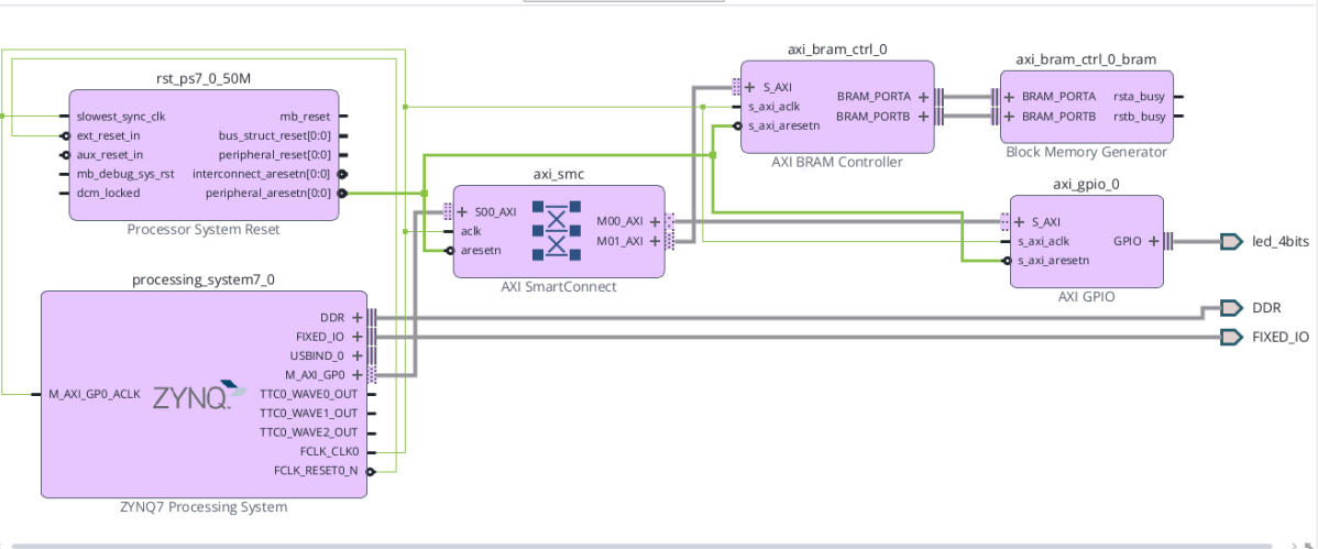
ZC706 Configurable Example Design (CED) block diagram
Base Design Components
Processing System (PS):
Zynq-7045 (XC7Z045-FFG900)
Dual-core Arm Cortex-A9 @ up to 800 MHz
DDR3 interface configured
Standard peripheral set enabled
PL Infrastructure:
AXI Interconnect (AXI SmartConnect)
AXI Block Memory Controller
AXI GPIO for LEDs
Processor System Reset module
Clock infrastructure (100 MHz default)
Processing System Specifications
Processor Configuration:
Dual Arm Cortex-A9 cores
32 KB L1 I-cache, 32 KB L1 D-cache per core
512 KB shared L2 cache
NEON SIMD extensions
VFPv3 floating point
Memory Interfaces:
DDR3: 1 GB (SODIMM) @ 533 MHz (1066 MT/s), 64-bit wide
QSPI: 128 Mb boot flash
OCM: 256 KB on-chip memory
Clock Configuration:
ZC706 Processing System Peripheral Mappings in the Configurable Example Design
Peripheral |
MIO Pins |
Function |
Notes |
|---|---|---|---|
UART1 |
MIO 48-49 |
Console UART |
115200 baud |
USB0 |
MIO 28-39 |
USB 2.0 Host/Device |
|
GEM0 |
MIO 16-27 |
Gigabit Ethernet |
|
SD0 |
MIO 40-45 |
SD Card |
4-bit mode |
QSPI |
MIO 1-6 |
Boot Flash |
Single I/O |
GPIO |
Multiple |
Buttons / LEDs |
N/A |
Programmable Logic Payload
The default payload is a basic platform with the following components:
AXI Interconnect
AXI Block Memory Controller
Block Memory Generator
AXI GPIO (LEDs)
Processor System Reset
ZC706 DDR Memory Map
ZC706 DDR3 Memory Specifications
Memory Type: DDR3 SDRAM
Capacity: 1 GB
Data Width: 64-bit
Speed: 533 MHz (1066 MT/s)
ZC706 DDR Memory Map Table
Start Address |
End Address |
Size |
Description |
Access |
Notes |
|---|---|---|---|---|---|
0x0000_0000 |
0x3FFF_FFFF |
1 GB |
DDR3 SDRAM |
R/W |
Main system memory |
ZC706 System Level Memory Map
The address map matches the ZC702 and preserves software compatibility.
Start Address |
Description |
|---|---|
0x00000000 |
DDR |
0xE0000000 |
PS peripherals |
0xF8000000 |
SLCR |
0xFC000000 |
QSPI linear |
0xFFFC0000 |
OCM |
ZC706 Additional Memory Regions for Programmable Logic Access
Start Address |
Description |
|---|---|
0x43C00000 |
Reserved for Custom AXI IP |
0x83C00000 |
Reserved for AXI IP through GP1 |
VPK120

The AMD VPK120 evaluation board.
Boot Firmware and Linux Disk Images
Boot Firmware Images - QSPI VPK120 - Boot Firmware + boot.bin:
Refer to Common Specifications
Linux Disk Image - Common Disk Image With Support for This Board
Refer to Common Specifications. For the SD card partition layout used as the secondary boot device, see EDF Disk Image Layout.
VPK120 System Controller Firmware Update
See the System Controller Wiki for more information https://xilinx-wiki.atlassian.net/wiki/x/AYCGhw
VPK120 DDR Memory Map
Start Address |
End Address |
Size |
Description |
Interface |
Access Type |
|---|---|---|---|---|---|
0x0000_0000_0000 |
0x7FFF_FFFF |
2 GB |
C0_DDR_LOW0 |
NoC_lpddr0/S00_INI |
R/W |
0x0008_0000_0000 |
0x0008_7FFF_FFFF |
2 GB |
C0_DDR_LOW1 |
NoC_lpddr0/S00_INI |
R/W |
0x0500_0000_0000 |
0x0500_FFFF_FFFF |
4 GB |
C0_DDR_CH1 |
NoC_lpddr1/S00_INI |
R/W |
0x0600_0000_0000 |
0x0600_FFFF_FFFF |
4 GB |
C0_DDR_CH2 |
NoC_lpddr2/S00_INI |
R/W |
0x0500_0000_0000 |
0x0500_FFFF_FFFF |
4 GB |
C1_DDR_CH1 |
NoC_lpddr1/S00_INI |
R/W |
0x0600_0000_0000 |
0x0600_FFFF_FFFF |
4 GB |
C1_DDR_CH2 |
NoC_lpddr2/S00_INI |
R/W |
0x0500_0000_0000 |
0x0500_FFFF_FFFF |
4 GB |
C2_DDR_CH1 |
NoC_lpddr0/S02_INI |
R/W |
0x0600_0000_0000 |
0x0600_FFFF_FFFF |
4 GB |
C2_DDR_CH2 |
NoC_lpddr0/S02_INI |
R/W |
0x0500_0000_0000 |
0x0500_FFFF_FFFF |
4 GB |
C3_DDR_CH1 |
NoC_lpddr0/S03_INI |
R/W |
0x0600_0000_0000 |
0x0600_FFFF_FFFF |
4 GB |
C3_DDR_CH2 |
NoC_lpddr0/S03_INI |
R/W |
DDR Configuration Summary:
Total DDR: Multiple LPDDR channels
Channel Configuration: 4 controllers (C0-C3)
Memory Type: LPDDR4/LPDDR5
Access: Through NoC (Network on Chip)
VPK120 System Level Memory Map
Start Address |
Description |
Size |
Type |
|---|---|---|---|
0x0000_0000_0000 |
DDR Low Memory Region 0 |
2 GB |
DDR |
0x0008_0000_0000 |
DDR Low Memory Region 1 |
2 GB |
DDR |
0x0500_0000_0000 |
DDR Channel 1 (All Controllers) |
4 GB |
DDR |
0x0600_0000_0000 |
DDR Channel 2 (All Controllers) |
4 GB |
DDR |
0xA400_0000 |
AXI BRAM Controller |
8 KB |
|
0xA401_0000 |
AXI GPIO 0 (LEDs) |
64 KB |
PL Peripheral |
0xA402_0000 |
AXI GPIO 1 (Push Buttons) |
64 KB |
PL Peripheral |
0xA403_0000 |
AXI GPIO 2 (DIP Switches) |
64 KB |
PL Peripheral |
0xF000_0000 |
CIPS Configuration Space |
PS Registers |
|
0xF100_0000 |
FPD Peripherals |
PS Peripherals |
|
0xF900_0000 |
LPD Peripherals |
PS Peripherals |
|
0xFE00_0000 |
PMC Peripherals |
||
0xFF00_0000 |
CPM/PCIe |
CPM |
PL Peripheral Details:
Base Address |
Peripheral |
Description |
Size |
|---|---|---|---|
0xA400_0000 |
Block RAM storage |
8 KB |
|
0xA401_0000 |
GPIO_0 |
LED control (gpio_led) |
64 KB |
0xA402_0000 |
GPIO_1 |
Push buttons (gpio_pb) |
64 KB |
0xA403_0000 |
GPIO_2 |
DIP switches (gpio_dp) |
64 KB |
VPK120 QSPI Memory Map
The VPK120 multidomain machine uses the edf-qspi recipe with the 256 MB
QSPI flash.
Start Address |
Description |
Size |
Source |
Purpose |
|---|---|---|---|---|
0x0000_0000 |
Image selector, primary |
384 KB |
|
Initial boot selection |
0x0006_0000 |
Image selector, backup |
384 KB |
|
Backup boot selection |
0x000C_0000 |
Image selector scratch |
128 KB |
Empty |
Reserved scratch space |
0x000E_0000 |
Image recovery |
20 MB |
|
Recovery boot image |
0x014E_0000 |
Image recovery scratch |
128 KB |
Empty |
Reserved scratch space |
0x0150_0000 |
Update metadata, primary |
128 KB |
|
Primary firmware update metadata |
0x0152_0000 |
Update metadata, backup |
128 KB |
|
Backup firmware update metadata |
0x0154_0000 |
U-Boot environment, primary |
128 KB |
Empty |
Reserved environment space |
0x0156_0000 |
U-Boot environment, backup |
128 KB |
Empty |
Reserved environment space |
0x0158_0000 |
Reserved / unallocated |
256 KB |
Empty |
Reserved space |
0x015C_0000 |
|
114.25 MB |
|
Primary boot firmware image |
0x0880_0000 |
|
114.25 MB |
|
Backup boot firmware image |
0x0FA4_0000 |
User scratch |
5.69 MB |
Empty |
Reserved user scratch space |
0x0FFF_0000 |
Manifest |
64 KB |
Manifest generated by |
QSPI image manifest |
Programing the SD Card / UFS (Secondary Boot device)
VPK120 Basic Board Interfaces
Key Interfaces (From Block Diagram):
PCIe Interface: PCIe EP GENx x16 connector
GTY/GTM Transceivers: Multiple high-speed serial interfaces
Memory:
LPDDR4/5 (2x channels shown)
1588 CLK for precision timing
Storage:
SD 3.0 card interface
OSPI/QSPI flash
USB: USB 2.0 ULPI interfaceNetworking:
Debug: JTAG interface
Expansion:
FMC+ connector
GPIO headers
System Management:
EMIO connections
Mictor debug connector
SMA connectors for clocking
VPK120 Powering the Board
Power Configuration:
VPK120 Default DIP Switch Settings - Boot
Boot Mode Configuration:
Based on typical Versal boot modes:
Boot Mode |
MODE[3:0] |
DIP Switch |
Description |
|---|---|---|---|
0000 |
SW1: OFF-OFF-OFF-OFF |
JTAG boot for debugging |
|
QSPI32 |
0010 |
SW1: OFF-OFF-ON-OFF |
Boot from QSPI x4 |
0001 |
SW1: OFF-OFF-OFF-ON |
Boot from OSPI x8 |
|
SD1_LS |
1110 |
SW1: ON-ON-ON-OFF |
Boot from SD card |
USB |
0111 |
SW1: OFF-ON-ON-ON |
USB boot mode |
Note: Actual DIP switch location and numbering should be verified with board silkscreen.
VPK120 UART Connections - FTDI-USB
UART Configuration:
Based on the block diagram showing PS/PMC connections:
UART Channel |
Source |
Destination |
Purpose |
Default Settings |
|---|---|---|---|---|
UART0 |
PS MIO |
FTDI CH A |
Linux/APU Console |
115200,8,N,1 |
UART1 |
PMC MIO |
FTDI CH B |
PMC/PLM Console |
115200,8,N,1 |
UART2 |
EMIO |
FTDI CH C |
115200,8,N,1 |
|
UART3 |
FTDI CH D |
Spare/User defined |
115200,8,N,1 |
VPK120 Base Vivado Design for BSPs and PS specifications
This specification inherits from the common and device specific specifications, but also has evaluation board specific items. See also the following:
VPK120 PL Board I/O
PL I/O Interfaces (From Block Diagram and CED):
Interface |
Type |
Location |
Description |
|---|---|---|---|
FMC+ Connector |
High-speed expansion |
PL banks |
FMC+ HPC standard interface |
GPIO Headers |
Digital I/O |
PL banks |
General purpose I/O |
EMIO Signals |
PS-PL interface |
XPIO block |
|
Mictor Connector |
Debug interface |
PL banks |
High-speed debug connector |
SMA Connectors |
RF/Clock I/O |
PL banks |
Sub-miniature coaxial connectors |
GTY/GTM Transceivers |
High-speed serial |
Dedicated banks |
Multi-gigabit transceivers |
PL Peripherals in CED:
Controller |
Base Address |
Description |
Direction |
|---|---|---|---|
axi_gpio_0 |
0xA401_0000 |
GPIO for LEDs (gpio_led) |
Output |
axi_gpio_1 |
0xA402_0000 |
GPIO for Push Buttons (gpio_pb) |
Input |
axi_gpio_2 |
0xA403_0000 |
GPIO for DIP Switches (gpio_dp) |
Input |
axi_bram_ctrl_0 |
0xA400_0000 |
BRAM Controller |
Bidirectional |
VPK120 MMI Configuration
Memory-Mapped Interface Components:
NoC (Network on Chip) Configuration:
Multiple NoC instances for DDR access
noc_lpddr0: Primary LPDDR interface
noc_lpddr1: Secondary LPDDR interface
noc_lpddr2: Additional LPDDR interface
aggr_noc: Aggregates NoC traffic
AXI Interfaces:
- M_AXI_FPD: Full Power Domain AXI master
- FPD_CCI_NOC_0-3: Cache Coherent Interconnect
- FPD_AXI_NOC_0-1: AXI NoC interfaces
- LPD_AXI_NOC_0: Low Power Domain AXI
- PMC_NOC_AXI_0: Platform Management Controller AXI
Memory Access Configuration:
VPK120 MMI Clocks
Clock Sources (From Block Diagram):
Primary Reference Clocks:
1588 CLK: IEEE 1588 precision timing clock
USB CLK: USB reference clock
PCIe Content: PCIe reference clock
Transceiver Reference Clocks:
PL Clock Distribution:
From CIPS:
Clock Frequencies (typical):
SMA Clock Connections:
Input/Output capable
Support for external reference clocks
Clock measurement and monitoring
VPK120 Reference PL Payload Information
See the Discovery and Evaluation
V80
Note
The Alveo V80 follows a different build and boot flow from the other Versal Gen 1 evaluation boards.
The Alveo Management Resource (AMR) documentation covers the V80 build, install, and board-management flows. Use these public AMR references with the EDF board notes in this section:
Alveo Management Resource Boot Firmware and Image Build Flows
The Alveo Management Resource (AMR) flow delivers the Alveo V80 boot
firmware, the card-install images, and the APU Linux image. Production
builds use the Yocto-based AMR flow with MACHINE=alveo-v80-amr:
bitbake emb-plus-ospi-amrbuilds the OSPI image set used for card installation.bitbake emb-plus-apu-imagebuilds the Linux image for the APU.
AMR 3.0.0 uses the same Yocto process for the RAVE and V80 boards. The
board-specific MACHINE value selects the output image set.
For development builds from AMR sources, use ./build.sh -profile v80.
The common-disk-image and OSPI boot-firmware descriptions in
Common Specifications do not
apply to V80.
The AMR host-to-card flow centers on PCIe. PF0 provides the management path that the Adaptive Management Interface (AMI) uses. PF1 provides the user or DMA-oriented path.
Supported Boot and Update Paths
The generic EDF boot-mode tables used for evaluation boards do not apply to V80. AMR 3.0.0 documents the following supported V80 build and update paths:
Path |
How AMR Uses It |
Reference |
|---|---|---|
Production OSPI image build |
Build the full installable image set with
|
|
APU Linux image build |
Build the APU Linux payload with
|
|
In-band image update over PCIe |
Use |
|
Out-of-band OSPI update over JTAG |
Use Vivado Hardware Manager or
|
DDR Memory Map
Memory Resource |
Size |
Address Range |
AMR Usage |
|---|---|---|---|
Discrete DDR4 |
4 GB |
|
RPU execution and host-to-RPU communication |
DDR4 DIMM |
32 GB |
|
Shared capacity memory for host, PL, and future APU growth |
HBM |
32 GB |
See the AMR V80 memory-map diagrams for the full HBM address view |
High-bandwidth application memory |
The current AMR V80 design uses one DDRMC for the 4 GB discrete DDR
and one DDRMC for the 32 GB DIMM. The public AMR
memory-resource guidance describes the HBM as two 16 GB stacks, with
each stack split into eight controllers and two 1 GB pseudo channels per
controller.
For the full remapped address diagrams and memory-controller notes, see the AMR V80 Memory Map and AMR V80 Memory Resources pages.
Programming/Flashing the ACAP Configuration Flash
AMR uses on-card OSPI flash as the primary install and update target for the V80 card.
Primary configuration path:
Use
ami_toolover PCIe when the existing flash partition table is already compatible with the incoming build.Use Vivado Hardware Manager over JTAG, or the
embpf-bootfw-update-toolcommand-line helper, when the AMR flow must installamr_ospi_fpt.binor recover the card.For step-by-step procedures, use the AMR install-card guide, AMR update-fpt guide, AMR update-pdi guide, and AMR JTAG recovery guide.
Basic Board Interfaces
Interface |
Type |
Specification |
|---|---|---|
PCIe |
CPM5 integrated Gen5 x8 |
PF0 management function (device ID |
HBM |
32 GB integrated |
Two 16 GB stacks used for high-bandwidth application memory |
Discrete DDR4 |
4 GB ECC |
RPU execution and host-to-RPU communication memory |
DDR4 DIMM |
32 GB ECC RDIMM |
Shared capacity memory for host, PL, and future APU growth |
QSFP56 |
4 ports |
PAM4 56G x4 per port |
GTM Transceivers |
GTM 209, 210, 112, 111 |
High-speed serial |
Configuration |
OSPI flash |
Primary AMR install and update target |
Storage |
eMMC |
64 GB |
Debug |
USB3 |
JTAG/UART through PMBus/SMBus |
Monitoring |
In-band AMR management over PCIe |
AMI to AMC communication through the AMR management stack |
Sensors |
I2C |
Card-level, component-level, and FPGA or HBM sensor access |
AMR manages the V80 card primarily through the in-band PCIe path. The current public release includes SMBus hardware support, but it does not include the SMBus firmware protocol.
Powering the Board
Power Requirements:
Main Power: 12 V through PCIe edge connector
Auxiliary Power:
12V_AUX_A (2x4 connector)
12V_AUX_B (2x4 connector)
Power Rails: 3.3 V aux/3.3 V/12 V
Power Management:
CPMS (GTY 105-102)
XLT SMBus interface
IPMI EEPROM for monitoring
UART Connections
Debug Interface:
PL Board I/O
High-Speed I/O:
Interface |
Banks |
Type |
Count |
|---|---|---|---|
QSFP56 Port 1 |
GTM 209 |
PAM4 56G x4 |
1 |
QSFP56 Port 2 |
GTM 210 |
PAM4 56G x4 |
1 |
QSFP56 Port 3 |
GTM 112 |
PAM4 56G x4 |
1 |
QSFP56 Port 4 |
GTM 111 |
PAM4 56G x4 |
1 |
Memory I/O:
Interface |
Banks |
Type |
|---|---|---|
DDR4 DIMM |
700-702, 703-705 |
64b+8b ECC |
MCIO |
GTY 200, 213, 214, 218 |
x4, x8, x4 configurations |
Expansion:
PCIe Gen5 edge connector
Expansion sideband through QSFP
NoC Configuration
NoC Architecture:
axi_noc_cipsconnects the CIPS PCIe host, PMC, and RPU to the PL apertures, discrete DDR, DIMM, and HBM resources.axi_noc_mc_ddr4_0serves the 4 GB discrete DDR used by the RPU and host-to-RPU communication paths.axi_noc_mc_ddr4_1serves the 32 GB DDR4 DIMM.The V80 AMR design does not currently use the PS APU, but the memory topology leaves room for future APU growth.
NoC Connections:
CPM_PCIE_NOC_0 and CPM_PCIE_NOC_1 provide the host-side PCIe access paths into PL apertures, DDR, DIMM, and HBM.
M00_AXIis the low-bandwidth PF0 management aperture.M01_AXIroutes to the PF1 SmartConnect and AXI GPIO test logic.M00_INIandM01_INIfeed the discrete DDR controller.M02_INIandM03_INIfeed the DIMM controller.The current AMR V80 design enables CIPS-side access to the full 32 GB HBM address space. User logic can add direct PL-to-HBM paths when it needs more bandwidth.
For the detailed connectivity matrices, port mappings, and address-remap diagrams, see the AMR V80 NoC configuration guide.
Alveo V80 CED Information
The following figure shows the generated block design:
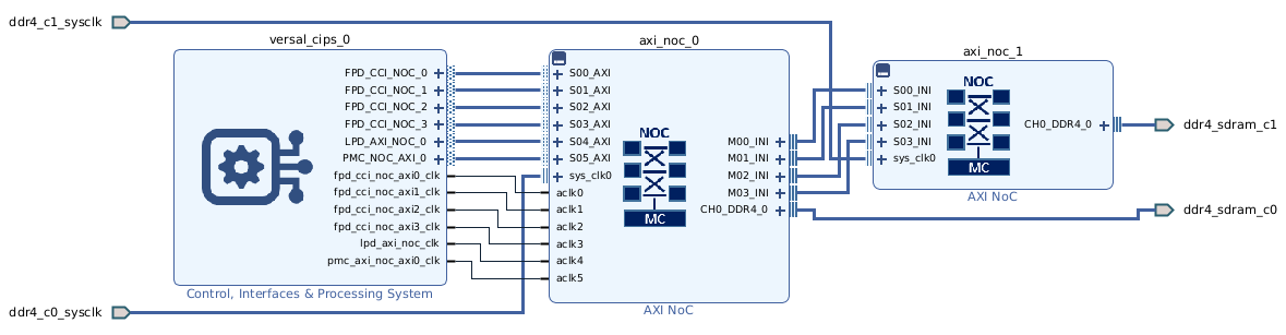
PL Payload:
The public AMR V80 base design keeps the PL payload intentionally small.
CPM5 provides integrated PCIe Gen5 x8 and integrated QDMA, so the design does not spend programmable-logic resources on soft PCIe or DMA.
The default PF1 hierarchy contains SmartConnect, AXI GPIO loopback, and reset synchronization logic for bring-up and validation.
User applications can extend the design to add QSFP, MCIO, PL, HBM, and DIMM data paths while reusing the AMR management and base-logic infrastructure.
PS Specifications:
The Alveo V80 AMR design configures the Versal device around the core CIPS blocks that matter for card management and host communication:
V80 PS Peripheral Mappings in the CED
High-Speed Interfaces:
CPM5 PCIe Gen5 x8: PF0 management and PF1 user or QDMA functions
GTM 209-210: QSFP56 Ports 1-2 (PAM4 56G x4)
GTM 111-112: QSFP56 Ports 3-4 (PAM4 56G x4)
GTY 200, 213, 214, 218: MCIO expansion interfaces
Memory Interfaces:
Discrete DDR4: 4 GB ECC for RPU execution and host-to-RPU messaging
DDR4 DIMM: 32 GB ECC RDIMM for shared capacity memory
HBM: 32 GB integrated high-bandwidth memory
Configuration & Management:
OSPI flash: primary AMR install and update target
eMMC: Bank 500 - 64 GB storage
SMBus: hardware path present, but not implemented in the current public AMR out-of-band management flow
PMBus: connected through USB3 for debug and service access
System Interfaces:
PCIe: Gen5 x8 edge connector
USB3: JTAG/UART0 debug interfaceBoard management: AMI to AMC communication over PCIe PF0
Clock Distribution:
sys_clk0: primary NoC clockExternal 200 MHz DDR clocks for discrete DDR, DIMM, and HBM resources
CIPS-generated clocks for PF1 logic and reset synchronization
Additional Payloads:
Network acceleration using the QSFP and MCIO interfaces
Application data paths that target HBM, DIMM, or both
Custom acceleration logic in the remaining PL, while reusing the AMR management framework
VHK158

The AMD VHK158 evaluation board.
Boot Firmware and Linux Disk Images
Boot Firmware Images - OSPI VHK158 - Boot Firmware + boot.bin
Refer to Common Specifications.
Linux Disk Image - Common Disk Image With Support for This Board
Refer to Common Specifications.
VHK158 OSPI Memory Map
The VHK158 multidomain machine uses the edf-ospi recipe with the 256 MB
OSPI flash. Build packagegroup-boot-artifacts to deploy the
individual boot artifacts and edf-ospi to assemble the complete flash
image.
Start Address |
Description |
Size |
Source |
Purpose |
|---|---|---|---|---|
0x0000_0000 |
Image selector, primary |
384 KB |
|
Initial boot selection |
0x0006_0000 |
Image selector, backup |
384 KB |
|
Backup boot selection |
0x000C_0000 |
Image selector scratch |
128 KB |
Empty |
Reserved scratch space |
0x000E_0000 |
Image recovery |
20 MB |
|
Recovery boot image |
0x014E_0000 |
Image recovery scratch |
128 KB |
Empty |
Reserved scratch space |
0x0150_0000 |
Update metadata, primary |
128 KB |
|
Primary firmware update metadata |
0x0152_0000 |
Update metadata, backup |
128 KB |
|
Backup firmware update metadata |
0x0154_0000 |
U-Boot environment, primary |
128 KB |
Empty |
Reserved environment space |
0x0156_0000 |
U-Boot environment, backup |
128 KB |
Empty |
Reserved environment space |
0x0158_0000 |
Reserved / unallocated |
256 KB |
Empty |
Reserved space |
0x015C_0000 |
|
114.25 MB |
|
Primary boot firmware image |
0x0880_0000 |
|
114.25 MB |
|
Backup boot firmware image |
0x0FA4_0000 |
User scratch |
5.63 MB |
Empty |
Reserved user scratch space |
0x0FFE_0000 |
Manifest |
128 KB |
Manifest generated by |
OSPI image manifest |
HBM Memory Validation on VHK158 Using memtester
The VHK158 platform exposes HBM as a dedicated memory bank in the
running device tree. This validation flow confirms that Linux can see the HBM
region and that memtester passes on the live address range. Boot the board
through the supported multistage OSPI -> SD flow with deferred
PL loading. Load the PL image from Linux as described below
before accessing HBM.
Prepare the board using the multistage boot procedure. See How to boot a board using the prebuilt images: Multi-stage boot (QSPI / OSPI -> UFS/SD) - Setup. Use OSPI as the primary boot medium and SD as the secondary boot media for this validation flow.
Boot the board and bring Linux to the shell. See Booting the Board to Linux - Power On.
Enter a root shell before installing packages or accessing
/dev/mem. Run the following commands as root.Confirm that
memtesteris present.Note
By default, this utility is not available in the Linux rootfs of the EDF platform disk image or the EDF Linux disk image. Install it from the EDF package feed for the matching board architecture.
Package availability can vary by release. For
vhk158the matching package-feed architecture iscortexa72_cortexa53. Use the RPM feed for the target EDF release wherememtesteris available, then install it on the running target with DNF.Check whether
memtesteris already present:# which memtester
Expected output:
which: no memtester in (/usr/local/sbin:/usr/local/bin:/usr/sbin:/usr/bin:/sbin:/bin)
Refresh the package metadata:
# dnf makecache
Example output. Exact version numbers and repository names vary by target release.
OE Remote Repo: sswreleases amd-edf 26.11 generic rpm rpm_latest all                          369  B/s | 123  B     00:00
OE Remote Repo: sswreleases amd-edf 26.11 generic rpm rpm_latest any                          433  B/s | 123  B     00:00
OE Remote Repo: sswreleases amd-edf 26.11 generic rpm rpm_latest noarch                       189 kB/s |  79 kB     00:00
OE Remote Repo: sswreleases amd-edf 26.11 generic rpm rpm_latest aarch64                      439  B/s | 123  B     00:00
OE Remote Repo: sswreleases amd-edf 26.11 generic rpm rpm_latest armv8a                       434  B/s | 123  B     00:00
OE Remote Repo: sswreleases amd-edf 26.11 generic rpm rpm_latest armv8a_crc                   427  B/s | 123  B     00:00
OE Remote Repo: sswreleases amd-edf 26.11 generic rpm rpm_latest cortexa72_cortexa53          1.9 MB/s | 1.6 MB     00:00
OE Remote Repo: sswreleases amd-edf 26.11 generic rpm rpm_latest versal_generic               425  B/s | 123  B     00:00
OE Remote Repo: sswreleases amd-edf 26.11 generic rpm rpm_latest amd_cortexa72_common         187 kB/s |  81 kB     00:00
Metadata cache created.
Install the package:
# dnf install memtester
Example output:
Last metadata expiration check: 0:00:11 ago on Wed Oct  7 02:40:55 2026.
Dependencies resolved.
==============================================================================================================================
Package
   Architecture        Version    Repository                                                                           Size
==============================================================================================================================
Installing:
memtester
   cortexa72_cortexa53 4.7.1-r0.0 oe-remote-repo-sswreleases-amd-edf-26.11-generic-rpm-rpm_latest-cortexa72_cortexa53  15 k

Transaction Summary
==============================================================================================================================
Install  1 Package

Total download size: 15 k
Installed size: 66 k
Is this ok [y/N]: y
Downloading Packages:
memtester-4.7.1-r0.0.cortexa72_cortexa53.rpm                                                   72 kB/s |  15 kB     00:00
------------------------------------------------------------------------------------------------------------------------------
Total                                                                                          71 kB/s |  15 kB     00:00
Running transaction check
Transaction check succeeded.
Running transaction test
Transaction test succeeded.
Running transaction
Preparing        :                                                                                                      1/1
Installing       : memtester-4.7.1-r0.0.cortexa72_cortexa53                                                             1/1

Installed:
memtester-4.7.1-r0.0.cortexa72_cortexa53

Complete!
Verify the install:
# which memtester
Result:
/usr/bin/memtester
Dump the running device tree and inspect the memory nodes.
# dtc -I fs -O dts /sys/firmware/devicetree/base > /tmp/running-device-tree.dts
# grep -n -A 12 -B 3 -E 'memory@|reserved-memory' /tmp/running-device-tree.dts
The live tree exposes the memory banks clearly:
293:    memory@4000000000 {
294-            device_type = "memory";
295-            compatible = "xlnx,axi-noc-1.1";
296-            reg = <0x40 0x00 0x08 0x00>;
297-            phandle = <0x07>;
298-            xlnx,ip-name = "axi_noc";
299-            memory_type = "memory";
300-    };
...
1037:           noc_ddr0_ddr_memory = "/memory@00000000";
1118:           noc_hbm_hbm_memory = "/memory@4000000000";
1128:           noc_ddr1_ddr_memory = "/memory@50000000000";
The board identifies the memory regions as follows:
memory@4000000000is the HBM bank.memory@00000000is DDR0.memory@50000000000is DDR1.
Caution
This physical-memory test is only suitable for bring-up on an otherwise idle board, with no kernel or application allocations in the HBM test window
0x4000000000-0x400fffffff. Thememtester -pcommand overwrites this entire 256 MiB window through/dev/memand does not reserve or exclusively allocate it. Testing memory in use can corrupt data or crash the system. An idle shell and the totals reported byfree -hdo not establish that this particular window is unused. Do not run the physical-memory test if you cannot establish that the window is unused and will remain unused throughout the test.The HBM bank shown below is online System RAM. The PL load is deferred until the Linux step below; this boot flow does not initialize the HBM paths before Linux starts. No software, including the kernel, may access HBM before that load. The captured log shows a successful run, but does not establish allocation isolation or that no HBM access occurred before the PL load.
Verify the visible memory banks from Linux.
# ls /proc/device-tree/memory@*
Output:
/proc/device-tree/memory@00000000:
compatible  device_type  memory_type  name  phandle  reg  xlnx,ip-name

/proc/device-tree/memory@4000000000:
compatible  device_type  memory_type  name  phandle  reg  xlnx,ip-name

/proc/device-tree/memory@50000000000:
compatible  device_type  memory_type  name  phandle  reg  xlnx,ip-name
Check the kernel memory map and the HBM range in
/proc/iomem.# grep "System RAM" /proc/iomem 00000000-097fffff : System RAM 09821000-0985efff : System RAM 09860000-0987ffff : System RAM 09900000-09967fff : System RAM 09a10000-7bf77fff : System RAM 7bf79000-7fe7ffff : System RAM 7fe90000-7fffffff : System RAM 800000000-b7fffffff : System RAM 4000000000-47ffffffff : System RAM 50000000000-503ffbfffff : System RAM 503ffc01000-503fffccfff : System RAM 503fffce000-503fffd0fff : System RAM 503ffff3000-503ffffffff : System RAM # cat /proc/iomem | grep 4000000000 4000000000-47ffffffff : System RAM
Load the PL image before any HBM access.
Note
In this EDF segmented design, the PL image configures the HBM NoC paths. Load the image before any software reads or writes the HBM memory region. Before the PDI loads, Linux and U-Boot cannot reach HBM
0x4000000000-0x47ffffffff. Accesses from Linux or U-Boot can hang. Confirm that the correct package is present, then load the matching PL image first.Load the package list and select the VHK158 PL image:
# dfx-mgr-client -listPackage
package list:
boot.pdi PL UUID: 7e87da1f

ID accelType   Base        slotLoc Accelerator
-- ----------- ----------- ------- -----------
 1 PL_FLAT     vrk160-p... -1      vrk160-pl-bram-gpio-fw
 2 RPU         rpu         -1      vrk160-r5-0-rpmsg_multi_services
 3 PL_FLAT     vrk160-r... -1      vrk160-revb-pl-bram-gpio-fw
 4 RPU         rpu         -1      vrk160-revb-r5-0-rpmsg_multi_services
 5 PL_FLAT     vmk180-p... -1      vmk180-pl-bram-gpio-fw
 6 RPU         rpu         -1      vmk180-r5-0-rpmsg_multi_services
 7 PL_FLAT     vpk360-p... -1      vpk360-pl-bram-gpio-fw
 8 PL_FLAT     vpk120-p... -1      vpk120-pl-bram-gpio-fw
 9 RPU         rpu         -1      vpk120-r5-0-rpmsg_multi_services
10 PL_FLAT     vrk165-r... -1      vrk165-revb-pl-bram-gpio-fw
11 RPU         rpu         -1      vrk165-revb-r5-0-rpmsg_multi_services
12 PL_FLAT     vck190-p... -1      vck190-pl-bram-gpio-fw
13 RPU         rpu         -1      vck190-r5-0-rpmsg_multi_services
14 PL_FLAT     vek280-p... -1      vek280-pl-bram-gpio-fw
15 RPU         rpu         -1      vek280-r5-0-rpmsg_multi_services
16 RPU         rpu         -1      versal-vpk360-r5-0-rpmsg_multi_services
17 RPU         rpu         -1      versal-vm-p-m1369-00-reva-x-prc-01-r5-0-rpmsg_multi_services
18 PL_FLAT     vrk165-p... -1      vrk165-pl-bram-gpio-fw
19 RPU         rpu         -1      vrk165-r5-0-rpmsg_multi_services
20 PL_FLAT     vpk180-p... -1      vpk180-pl-bram-gpio-fw
21 RPU         rpu         -1      vpk180-r5-0-rpmsg_multi_services
22 PL_FLAT     vhk158-p... -1      vhk158-pl-bram-gpio-fw
23 RPU         rpu         -1      vhk158-r5-0-rpmsg_multi_services
Load the PL PDI for the target board:
# dfx-mgr-client -loadByName vhk158-pl-bram-gpio-fw
Example output:
[246770.476]Loading PDI from DDR
[246770.770]0.310 ms: PDI initialization time
[246774.629]+++Loading Image#: 0x0, Name: CONFIG_MASTER, Id: 0x18700001
[246780.942]---Loading Partition#: 0x0, Id: 0x100
[246993.988] 208.633 ms for Partition#: 0x0, Size: 3251728 Bytes
vhk158-pl-bram-gpio-fw: Loaded with slot_handle 0 (FPGA state: operating)
After the PDI loads, you can use the HBM address range for the remaining validation steps.
Validate the overall memory footprint and then access the HBM base address.
# free -h
               total        used        free      shared  buff/cache   available
Mem:            62Gi       822Mi        62Gi        11Mi       260Mi        61Gi
Swap:             0B          0B          0B

# dd if=/dev/mem of=/dev/null bs=4096 count=1 skip=$((0x4000000000/4096))
1+0 records in
1+0 records out
4096 bytes (4.1 kB, 4.0 KiB) copied, 5.987e-05 s, 68.4 MB/s
Run
memtesterdirectly on the HBM address range.# memtester -p 0x4000000000 -d /dev/mem 256M 1
Output:
memtester version 4.7.1 (64-bit)
Copyright (C) 2001-2024 Charles Cazabon.
Licensed under the GNU General Public License version 2 (only).

pagesize is 4096
pagesizemask is 0xfffffffffffff000
want 256MB (268435456 bytes)
Loop 1/1:
  Stuck Address       : ok
  Random Value        : ok
  Compare XOR         : ok
  Compare SUB         : ok
  Compare MUL         : ok
  Compare DIV         : ok
  Compare OR          : ok
  Compare AND         : ok
  Sequential Increment: ok
  Solid Bits          : ok
  Block Sequential    : ok
  Checkerboard        : ok
  Bit Spread          : ok
  Bit Flip            : ok
  Walking Ones        : ok
  Walking Zeroes      : ok

Done.
This flow confirms that the VHK158 HBM region is present at
0x4000000000 and that the live memory test passes on the target board.
VHK158 HBM memtester log
Connecting to device com0. Use Ctrl-\ to escape.
[0.181]Non Secure Boot
[3.037]Loading PDI from OSPI
[6.109]3.089 ms: PDI initialization time
[6.142]+++Loading Image#: 0x1, Name: lpd, Id: 0x04210002
[6.184]---Loading Partition#: 0x1, Id: 0xC
[21.910] 15.692 ms for Partition#: 0x1, Size: 9616 Bytes
**********************************************
Image Selector App Start
**********************************************
******** Boot info ********
Boot Count: 1
MaxBootCnt: 4
Rollback counter: 322E31
******** Metadata info ********
Mdata.crc32: B108553E
Mdata.version: 2
Mdata.active_index: 0
Mdata.previous_active_index: 1
Mdata.metadata_size: 7C
Mdata.desc_offset: 20
Mdata.bank_state[0]: FC
Mdata.bank_state[1]: FC
Mdata.bank_state[2]: FF
Mdata.bank_state[3]: FF
Mdata.fw_desc.num_banks: 2
Mdata.fw_desc.num_images: 1
Mdata.fw_desc.img_entry_size: 50
Mdata.fw_desc.bank_info_entry_size: 18
******** Guid info ********
Image Type Guid: 19A5F8E3-4BD2-4F01-863C-7BB2D43F82A7
Location Guid: D7CE8A58-CE2C-11ED-81CD-D324E93AC223
Image Guid: 7E1B930B-F6B2-EF11-8565-EB65D140066B
Image Acceptance: yes
Image Guid: 00D84312-F6B2-EF11-8F4F-8BDDC3AA326D
Image Acceptance: yes
******** Image Selector version info ********
Functional Description : Image Selector (versal-vhk158-multidomain)
Functional Version : 1.2
Tools Version : 2026.2
Build info : S10051950
******** Active bank version info ********
Functional Description : AMD EDF Boot Firmware (versal-vhk158-multidomain)
Functional Version : 1.2
Tools Version : 2026.2
Build info : S10051950
******** Image Selection info ********
Reset the Boot counter as bank 0 is in accepted state
Updated bank 0 to boot part register
[0.012]****************************************
[0.045]Xilinx Versal Platform Loader and Manager
[0.079]Release 2026.2 Oct 5 2026 - 18:03:13
[0.115]Platform Version: v2.0 PMC: v2.0, PS: v2.0
[0.153]BOOTMODE: 0x8, MULTIBOOT: 0x2B8
[0.183]****************************************
[0.414]Non Secure Boot
[3.400]PLM Initialization Time
[3.424]***********Boot PDI Load: Started***********
[3.479]Loading PDI from OSPI
[6.666]3.204 ms: PDI initialization time
[6.699]+++Loading Image#: 0x1, Name: SUB_SYSTEM_BOOT, Id: 0x18700000
[6.749]---Loading Partition#: 0x1, Id: 0x2
[28.680] 21.898 ms for Partition#: 0x1, Size: 364912 Bytes
[28.737]+++Loading Image#: 0x2, Name: lpd, Id: 0x04210002
[28.780]---Loading Partition#: 0x2, Id: 0xC
[92.195] 63.380 ms for Partition#: 0x2, Size: 9616 Bytes
[97.148]---Loading Partition#: 0x3, Id: 0x0
[102.790] 1.754 ms for Partition#: 0x3, Size: 49664 Bytes
PSM Firmware version: 2026.2 [Build: Oct 5 2026 18:03:13 ]
[111.511]+++Loading Image#: 0x3, Name: fpd, Id: 0x0420C003
[116.668]---Loading Partition#: 0x4, Id: 0x8
[121.233] 0.593 ms for Partition#: 0x4, Size: 4224 Bytes
[125.657]+++Loading Image#: 0x4, Name: CONFIG_MASTER, Id: 0x18700000
[131.699]---Loading Partition#: 0x5, Id: 0x13
[992.846] 857.085 ms for Partition#: 0x5, Size: 671424 Bytes
[995.613]+++Loading Image#: 0x5, Name: apu_ss, Id: 0x1C000000
[1000.794]---Loading Partition#: 0x6, Id: 0x0
[1007.306] 2.448 ms for Partition#: 0x6, Size: 81536 Bytes
[1010.045]---Loading Partition#: 0x7, Id: 0x0
[1015.589] 1.481 ms for Partition#: 0x7, Size: 49152 Bytes
[1019.295]---Loading Partition#: 0x8, Id: 0x0
[1023.675] 0.318 ms for Partition#: 0x8, Size: 10272 Bytes
[1028.544]---Loading Partition#: 0x9, Id: 0x0
[1077.773] 45.166 ms for Partition#: 0x9, Size: 1511696 Bytes
[1080.362]---Loading Partition#: 0xA, Id: 0x0
[1084.502] 0.080 ms for Partition#: 0xA, Size: 2080 Bytes
[1089.521]---Loading Partition#: 0xB, Id: 0x0
[1096.633] 3.052 ms for Partition#: 0xB, Size: 101696 Bytes
[1099.466]***********Boot PDI Load: Done***********
[1103.626]33.784 ms: ROM Time
[1106.304]Total PLM Boot Time
NOTICE: TF-A running on SILICON 0
RPU0I REMOTL: registeriug: 0, name=ff350000.mailbox
RPU0: RTICT:: regi: erin4: 1, name=):cl000rlibme-v2_1io_desc0-RPU0: REMOTE: r
gistCE:n B 3, nami=9 :c06011:01e Slp io_desc1
ROU0:E:E RTE:t egosteria : 3, SaEM_S9UT000.libmetal_uio_data
RPU
: REMOTE: registeCinS: 4E nRmS=ffo0 000.Ei_er
ET2 instead.
RPU0: REMOTE: IRQ and shared memory
RPU0: REMOTE: Wait for echo test to start.
U-Boot 2026.01 (Sep 30 2026 - 14:32:14 +0000)
CPU: Versal
Silicon: v2
Model: Xilinx Versal vhk158 Eval board revA
DRAM: 2 GiB (total 64 GiB)
EL Level: EL2
Multiboot: 0
Xilinx I2C FRU format at nvmem0:
Manufacturer Name: XILINX
Product Name: VHK158
Serial No: 511201B01011
Part Number: 430511201
File ID: 0x0
Revision Number: B01
Core: 38 devices, 25 uclasses, devicetree: board
MMC: mmc@f1050000: 0
Loading Environment from SPIFlash... SF: Detected mt35xu02g with page size 256 Bytes, erase size 128 KiB, total 256 MiB
OK
In: serial@ff000000
Out: serial@ff000000
Err: serial@ff000000
Net:
ZYNQ GEM: ff0c0000, mdio bus ff0c0000, phyaddr 1, interface rgmii-id
eth0: ethernet@ff0c0000
starting USB...
Starting the controller
USB XHCI 1.10
Bus usb@fe200000: 2 USB Device(s) found
scanning usb for storage devices... 1 Storage Device(s) found
Hit any key to stop autoboot: 0
Missing TPMv2 device for EFI_TCG_PROTOCOL
Missing RNG device for EFI_RNG_PROTOCOL
*** U-Boot Boot Menu ***
usb 0
mmc 0
0. Exit
Press UP/DOWN to move, ENTER to select, ESC to quit
Loading Boot0000 'usb 0' failed
Loading from BootNext failed, falling back to BootOrder
Loading Boot0000 'usb 0' failed
Booting: Label: mmc 0 Device path: /VenHw(e61d73b9-a384-4acc-aeab-82e828f3628b,0000000000000000)/VenHw(e61d73b9-a384-4acc-aeab-82e828f3628b,7000000000000000)/SD(0)/SD(0)
No RNG device
EDF Linux
EDF Xen
─────────────────────
Boot in 1s.
Removing MTD device #0 (nor0) with use count 1
[ 0.000000] Booting Linux on physical CPU 0x0000000000 [0x410fd083]
[ 0.000000] Linux version 6.18.40-xilinx-g2d84e454c4b3 (oe-user@oe-host) (aarch64-amd-linux-gcc (GCC) 15.3.0, GNU ld (GNU Binutils) 2.46.1.20260718) #1 SMP Wed Sep 30 14:04:08 UTC 2026
[ 0.000000] KASLR disabled due to lack of seed
[ 0.000000] Machine model: Xilinx Versal vhk158 Eval board revA
[ 0.000000] earlycon: pl11 at MMIO32 0x00000000ff000000 (options '115200')
[ 0.000000] printk: legacy bootconsole [pl11] enabled
[ 0.000000] efi: EFI v2.11 by Das U-Boot
[ 0.000000] efi: ESRT=0x503fffcb040 RTPROP=0x503fffcd040 SMBIOS 3.0=0x7bf78000 MEMRESERVE=0x503fff6c040
[ 0.000000] esrt: Reserving ESRT space from 0x00000503fffcb040 to 0x00000503fffcb078.
[ 0.000000] OF: reserved mem: 0x0000000009880000..0x0000000009883fff (16 KiB) nomap non-reusable vdev0vring0@9880000
[ 0.000000] OF: reserved mem: 0x0000000009884000..0x0000000009887fff (16 KiB) nomap non-reusable vdev0vring1@9884000
[ 0.000000] Reserved memory: created DMA memory pool at 0x0000000009888000, size 0 MiB
[ 0.000000] OF: reserved mem: initialized node vdev0buffer@9888000, compatible id shared-dma-pool
[ 0.000000] OF: reserved mem: 0x0000000009888000..0x00000000098fffff (480 KiB) nomap non-reusable vdev0buffer@9888000
[ 0.000000] OF: reserved mem: 0x000000000985f000..0x000000000985ffff (4 KiB) nomap non-reusable trace@985f000
[ 0.000000] OF: reserved mem: 0x0000000009800000..0x000000000981ffff (128 KiB) nomap non-reusable rproc0@9800000
[ 0.000000] OF: reserved mem: 0x0000000009820000..0x00000000098200ff (0 KiB) nomap non-reusable rsctbl@9820000
[ 0.000000] OF: reserved mem: 0x0000000009968000..0x00000000099c7fff (384 KiB) nomap non-reusable libmetal_elf@9968000
[ 0.000000] OF: reserved mem: 0x00000000099c8000..0x00000000099cbfff (16 KiB) nomap non-reusable libmetal_desc0@99c8000
[ 0.000000] OF: reserved mem: 0x00000000099cc000..0x00000000099cffff (16 KiB) nomap non-reusable libmetal_desc1@99cc000
[ 0.000000] OF: reserved mem: 0x00000000099d0000..0x0000000009a0ffff (256 KiB) nomap non-reusable libmetal_data@99d0000
[ 0.000000] Zone ranges:
[ 0.000000] DMA [mem 0x0000000000000000-0x00000000ffffffff]
[ 0.000000] DMA32 empty
[ 0.000000] Normal [mem 0x0000000100000000-0x00000503ffffffff]
[ 0.000000] Movable zone start for each node
[ 0.000000] Early memory node ranges
[ 0.000000] node 0: [mem 0x0000000000000000-0x00000000097fffff]
[ 0.000000] node 0: [mem 0x0000000009800000-0x0000000009820fff]
[ 0.000000] node 0: [mem 0x0000000009821000-0x000000000985efff]
[ 0.000000] node 0: [mem 0x000000000985f000-0x000000000985ffff]
[ 0.000000] node 0: [mem 0x0000000009860000-0x000000000987ffff]
[ 0.000000] node 0: [mem 0x0000000009880000-0x00000000098fffff]
[ 0.000000] node 0: [mem 0x0000000009900000-0x0000000009967fff]
[ 0.000000] node 0: [mem 0x0000000009968000-0x0000000009a0ffff]
[ 0.000000] node 0: [mem 0x0000000009a10000-0x000000007bf77fff]
[ 0.000000] node 0: [mem 0x000000007bf78000-0x000000007bf78fff]
[ 0.000000] node 0: [mem 0x000000007bf79000-0x000000007fe7ffff]
[ 0.000000] node 0: [mem 0x000000007fe80000-0x000000007fe8ffff]
[ 0.000000] node 0: [mem 0x000000007fe90000-0x000000007fffffff]
[ 0.000000] node 0: [mem 0x0000000800000000-0x0000000b7fffffff]
[ 0.000000] node 0: [mem 0x0000004000000000-0x00000047ffffffff]
[ 0.000000] node 0: [mem 0x0000050000000000-0x00000503ffbfffff]
[ 0.000000] node 0: [mem 0x00000503ffc00000-0x00000503ffc00fff]
[ 0.000000] node 0: [mem 0x00000503ffc01000-0x00000503fffccfff]
[ 0.000000] node 0: [mem 0x00000503fffcd000-0x00000503fffcdfff]
[ 0.000000] node 0: [mem 0x00000503fffce000-0x00000503fffd0fff]
[ 0.000000] node 0: [mem 0x00000503fffd1000-0x00000503ffff2fff]
[ 0.000000] node 0: [mem 0x00000503ffff3000-0x00000503ffffffff]
[ 0.000000] Initmem setup node 0 [mem 0x0000000000000000-0x00000503ffffffff]
[ 0.000000] cma: Reserved 256 MiB at 0x000000006be00000
[ 0.000000] psci: probing for conduit method from DT.
[ 0.000000] psci: PSCIv1.1 detected in firmware.
[ 0.000000] psci: Using standard PSCI v0.2 function IDs
[ 0.000000] psci: MIGRATE_INFO_TYPE not supported.
[ 0.000000] psci: SMC Calling Convention v1.5
[ 0.000000] percpu: Embedded 32 pages/cpu s90392 r8192 d32488 u131072
[ 0.000000] Detected PIPT I-cache on CPU0
[ 0.000000] CPU features: detected: GICv3 CPU interface
[ 0.000000] CPU features: detected: Spectre-v2
[ 0.000000] CPU features: detected: Spectre-v3a
[ 0.000000] CPU features: detected: Spectre-BHB
[ 0.000000] CPU features: detected: ARM erratum 1742098
[ 0.000000] CPU features: detected: ARM errata 1165522, 1319367, or 1530923
[ 0.000000] alternatives: applying boot alternatives
[ 0.000000] Kernel command line: root=PARTUUID=556fd79e-7c1c-471c-b07e-6e5779400de4 ro rootwait earlycon uio_pdrv_genirq.of_id=generic-uio
[ 0.000000] printk: log buffer data + meta data: 65536 + 229376 = 294912 bytes
[ 0.000000] Dentry cache hash table entries: 8388608 (order: 14, 67108864 bytes, linear)
[ 0.000000] Inode-cache hash table entries: 4194304 (order: 13, 33554432 bytes, linear)
[ 0.000000] software IO TLB: area num 2.
[ 0.000000] software IO TLB: mapped [mem 0x0000000067e00000-0x000000006be00000] (64MB)
[ 0.000000] Built 1 zonelists, mobility grouping on. Total pages: 16777216
[ 0.000000] mem auto-init: stack:all(zero), heap alloc:off, heap free:off
[ 0.000000] SLUB: HWalign=64, Order=0-3, MinObjects=0, CPUs=2, Nodes=1
[ 0.000000] rcu: Hierarchical RCU implementation.
[ 0.000000] rcu: RCU event tracing is enabled.
[ 0.000000] rcu: RCU restricting CPUs from NR_CPUS=16 to nr_cpu_ids=2.
[ 0.000000] Tracing variant of Tasks RCU enabled.
[ 0.000000] rcu: RCU calculated value of scheduler-enlistment delay is 25 jiffies.
[ 0.000000] rcu: Adjusting geometry for rcu_fanout_leaf=16, nr_cpu_ids=2
[ 0.000000] RCU Tasks Trace: Setting shift to 1 and lim to 1 rcu_task_cb_adjust=1 rcu_task_cpu_ids=2.
[ 0.000000] NR_IRQS: 64, nr_irqs: 64, preallocated irqs: 0
[ 0.000000] GICv3: GIC: Using split EOI/Deactivate mode
[ 0.000000] GICv3: 160 SPIs implemented
[ 0.000000] GICv3: 0 Extended SPIs implemented
[ 0.000000] Root IRQ handler: gic_handle_irq
[ 0.000000] GICv3: GICv3 features: 16 PPIs
[ 0.000000] GICv3: GICD_CTLR.DS=0, SCR_EL3.FIQ=1
[ 0.000000] GICv3: CPU0: found redistributor 0 region 0:0x00000000f9080000
[ 0.000000] ITS [mem 0xf9020000-0xf903ffff]
[ 0.000000] ITS@0x00000000f9020000: allocated 65536 Devices @800100000 (flat, esz 8, psz 64K, shr 0)
[ 0.000000] ITS: using cache flushing for cmd queue
[ 0.000000] GICv3: using LPI property table @0x0000000800180000
[ 0.000000] GIC: using cache flushing for LPI property table
[ 0.000000] GICv3: CPU0: using allocated LPI pending table @0x0000000800190000
[ 0.000000] rcu: srcu_init: Setting srcu_struct sizes based on contention.
[ 0.000000] clocksource: jiffies: mask: 0xffffffff max_cycles: 0xffffffff, max_idle_ns: 7645041785100000 ns
[ 0.000000] arch_timer: cp15 timer running at 99.99MHz (phys).
[ 0.000000] clocksource: arch_sys_counter: mask: 0x1ffffffffffffff max_cycles: 0x171015c90f, max_idle_ns: 440795203080 ns
[ 0.000000] sched_clock: 57 bits at 100MHz, resolution 10ns, wraps every 4398046511101ns
[ 0.008391] Console: colour dummy device 80x25
[ 0.012877] printk: legacy console [tty0] enabled
[ 0.017623] printk: legacy bootconsole [pl11] disabled
[ 0.000000] Booting Linux on physical CPU 0x0000000000 [0x410fd083]
[ 0.000000] Linux version 6.18.40-xilinx-g2d84e454c4b3 (oe-user@oe-host) (aarch64-amd-linux-gcc (GCC) 15.3.0, GNU ld (GNU Binutils) 2.46.1.20260718) #1 SMP Wed Sep 30 14:04:08 UTC 2026
[ 0.000000] KASLR disabled due to lack of seed
[ 0.000000] Machine model: Xilinx Versal vhk158 Eval board revA
[ 0.000000] earlycon: pl11 at MMIO32 0x00000000ff000000 (options '115200')
[ 0.000000] printk: legacy bootconsole [pl11] enabled
[ 0.000000] efi: EFI v2.11 by Das U-Boot
[ 0.000000] efi: ESRT=0x503fffcb040 RTPROP=0x503fffcd040 SMBIOS 3.0=0x7bf78000 MEMRESERVE=0x503fff6c040
[ 0.000000] esrt: Reserving ESRT space from 0x00000503fffcb040 to 0x00000503fffcb078.
[ 0.000000] OF: reserved mem: 0x0000000009880000..0x0000000009883fff (16 KiB) nomap non-reusable vdev0vring0@9880000
[ 0.000000] OF: reserved mem: 0x0000000009884000..0x0000000009887fff (16 KiB) nomap non-reusable vdev0vring1@9884000
[ 0.000000] Reserved memory: created DMA memory pool at 0x0000000009888000, size 0 MiB
[ 0.000000] OF: reserved mem: initialized node vdev0buffer@9888000, compatible id shared-dma-pool
[ 0.000000] OF: reserved mem: 0x0000000009888000..0x00000000098fffff (480 KiB) nomap non-reusable vdev0buffer@9888000
[ 0.000000] OF: reserved mem: 0x000000000985f000..0x000000000985ffff (4 KiB) nomap non-reusable trace@985f000
[ 0.000000] OF: reserved mem: 0x0000000009800000..0x000000000981ffff (128 KiB) nomap non-reusable rproc0@9800000
[ 0.000000] OF: reserved mem: 0x0000000009820000..0x00000000098200ff (0 KiB) nomap non-reusable rsctbl@9820000
[ 0.000000] OF: reserved mem: 0x0000000009968000..0x00000000099c7fff (384 KiB) nomap non-reusable libmetal_elf@9968000
[ 0.000000] OF: reserved mem: 0x00000000099c8000..0x00000000099cbfff (16 KiB) nomap non-reusable libmetal_desc0@99c8000
[ 0.000000] OF: reserved mem: 0x00000000099cc000..0x00000000099cffff (16 KiB) nomap non-reusable libmetal_desc1@99cc000
[ 0.000000] OF: reserved mem: 0x00000000099d0000..0x0000000009a0ffff (256 KiB) nomap non-reusable libmetal_data@99d0000
[ 0.000000] Zone ranges:
[ 0.000000] DMA [mem 0x0000000000000000-0x00000000ffffffff]
[ 0.000000] DMA32 empty
[ 0.000000] Normal [mem 0x0000000100000000-0x00000503ffffffff]
[ 0.000000] Movable zone start for each node
[ 0.000000] Early memory node ranges
[ 0.000000] node 0: [mem 0x0000000000000000-0x00000000097fffff]
[ 0.000000] node 0: [mem 0x0000000009800000-0x0000000009820fff]
[ 0.000000] node 0: [mem 0x0000000009821000-0x000000000985efff]
[ 0.000000] node 0: [mem 0x000000000985f000-0x000000000985ffff]
[ 0.000000] node 0: [mem 0x0000000009860000-0x000000000987ffff]
[ 0.000000] node 0: [mem 0x0000000009880000-0x00000000098fffff]
[ 0.000000] node 0: [mem 0x0000000009900000-0x0000000009967fff]
[ 0.000000] node 0: [mem 0x0000000009968000-0x0000000009a0ffff]
[ 0.000000] node 0: [mem 0x0000000009a10000-0x000000007bf77fff]
[ 0.000000] node 0: [mem 0x000000007bf78000-0x000000007bf78fff]
[ 0.000000] node 0: [mem 0x000000007bf79000-0x000000007fe7ffff]
[ 0.000000] node 0: [mem 0x000000007fe80000-0x000000007fe8ffff]
[ 0.000000] node 0: [mem 0x000000007fe90000-0x000000007fffffff]
[ 0.000000] node 0: [mem 0x0000000800000000-0x0000000b7fffffff]
[ 0.000000] node 0: [mem 0x0000004000000000-0x00000047ffffffff]
[ 0.000000] node 0: [mem 0x0000050000000000-0x00000503ffbfffff]
[ 0.000000] node 0: [mem 0x00000503ffc00000-0x00000503ffc00fff]
[ 0.000000] node 0: [mem 0x00000503ffc01000-0x00000503fffccfff]
[ 0.000000] node 0: [mem 0x00000503fffcd000-0x00000503fffcdfff]
[ 0.000000] node 0: [mem 0x00000503fffce000-0x00000503fffd0fff]
[ 0.000000] node 0: [mem 0x00000503fffd1000-0x00000503ffff2fff]
[ 0.000000] node 0: [mem 0x00000503ffff3000-0x00000503ffffffff]
[ 0.000000] Initmem setup node 0 [mem 0x0000000000000000-0x00000503ffffffff]
[ 0.000000] cma: Reserved 256 MiB at 0x000000006be00000
[ 0.000000] psci: probing for conduit method from DT.
[ 0.000000] psci: PSCIv1.1 detected in firmware.
[ 0.000000] psci: Using standard PSCI v0.2 function IDs
[ 0.000000] psci: MIGRATE_INFO_TYPE not supported.
[ 0.000000] psci: SMC Calling Convention v1.5
[ 0.000000] percpu: Embedded 32 pages/cpu s90392 r8192 d32488 u131072
[ 0.000000] Detected PIPT I-cache on CPU0
[ 0.000000] CPU features: detected: GICv3 CPU interface
[ 0.000000] CPU features: detected: Spectre-v2
[ 0.000000] CPU features: detected: Spectre-v3a
[ 0.000000] CPU features: detected: Spectre-BHB
[ 0.000000] CPU features: detected: ARM erratum 1742098
[ 0.000000] CPU features: detected: ARM errata 1165522, 1319367, or 1530923
[ 0.000000] alternatives: applying boot alternatives
[ 0.000000] Kernel command line: root=PARTUUID=556fd79e-7c1c-471c-b07e-6e5779400de4 ro rootwait earlycon uio_pdrv_genirq.of_id=generic-uio
[ 0.000000] printk: log buffer data + meta data: 65536 + 229376 = 294912 bytes
[ 0.000000] Dentry cache hash table entries: 8388608 (order: 14, 67108864 bytes, linear)
[ 0.000000] Inode-cache hash table entries: 4194304 (order: 13, 33554432 bytes, linear)
[ 0.000000] software IO TLB: area num 2.
[ 0.000000] software IO TLB: mapped [mem 0x0000000067e00000-0x000000006be00000] (64MB)
[ 0.000000] Built 1 zonelists, mobility grouping on. Total pages: 16777216
[ 0.000000] mem auto-init: stack:all(zero), heap alloc:off, heap free:off
[ 0.000000] SLUB: HWalign=64, Order=0-3, MinObjects=0, CPUs=2, Nodes=1
[ 0.000000] rcu: Hierarchical RCU implementation.
[ 0.000000] rcu: RCU event tracing is enabled.
[ 0.000000] rcu: RCU restricting CPUs from NR_CPUS=16 to nr_cpu_ids=2.
[ 0.000000] Tracing variant of Tasks RCU enabled.
[ 0.000000] rcu: RCU calculated value of scheduler-enlistment delay is 25 jiffies.
[ 0.000000] rcu: Adjusting geometry for rcu_fanout_leaf=16, nr_cpu_ids=2
[ 0.000000] RCU Tasks Trace: Setting shift to 1 and lim to 1 rcu_task_cb_adjust=1 rcu_task_cpu_ids=2.
[ 0.000000] NR_IRQS: 64, nr_irqs: 64, preallocated irqs: 0
[ 0.000000] GICv3: GIC: Using split EOI/Deactivate mode
[ 0.000000] GICv3: 160 SPIs implemented
[ 0.000000] GICv3: 0 Extended SPIs implemented
[ 0.000000] Root IRQ handler: gic_handle_irq
[ 0.000000] GICv3: GICv3 features: 16 PPIs
[ 0.000000] GICv3: GICD_CTLR.DS=0, SCR_EL3.FIQ=1
[ 0.000000] GICv3: CPU0: found redistributor 0 region 0:0x00000000f9080000
[ 0.000000] ITS [mem 0xf9020000-0xf903ffff]
[ 0.000000] ITS@0x00000000f9020000: allocated 65536 Devices @800100000 (flat, esz 8, psz 64K, shr 0)
[ 0.000000] ITS: using cache flushing for cmd queue
[ 0.000000] GICv3: using LPI property table @0x0000000800180000
[ 0.000000] GIC: using cache flushing for LPI property table
[ 0.000000] GICv3: CPU0: using allocated LPI pending table @0x0000000800190000
[ 0.000000] rcu: srcu_init: Setting srcu_struct sizes based on contention.
[ 0.000000] clocksource: jiffies: mask: 0xffffffff max_cycles: 0xffffffff, max_idle_ns: 7645041785100000 ns
[ 0.000000] arch_timer: cp15 timer running at 99.99MHz (phys).
[ 0.000000] clocksource: arch_sys_counter: mask: 0x1ffffffffffffff max_cycles: 0x171015c90f, max_idle_ns: 440795203080 ns
[ 0.000000] sched_clock: 57 bits at 100MHz, resolution 10ns, wraps every 4398046511101ns
[ 0.008391] Console: colour dummy device 80x25
[ 0.012877] printk: legacy console [tty0] enabled
[ 0.017623] printk: legacy bootconsole [pl11] disabled
[ 0.022833] Calibrating delay loop (skipped), value calculated using timer frequency.. 199.99 BogoMIPS (lpj=399996)
[ 0.022845] pid_max: default: 32768 minimum: 301
[ 0.023074] Mount-cache hash table entries: 131072 (order: 8, 1048576 bytes, linear)
[ 0.023211] Mountpoint-cache hash table entries: 131072 (order: 8, 1048576 bytes, linear)
[ 0.024443] rcu: Hierarchical SRCU implementation.
[ 0.024457] rcu: Max phase no-delay instances is 1000.
[ 0.024601] Timer migration: 1 hierarchy levels; 8 children per group; 1 crossnode level
+q6E616D65[ 0.024845] Remapping and enabling EFI services.
[ 0.024966] smp: Bringing up secondary CPUs ...
[ 0.097249] Detected PIPT I-cache on CPU1
[ 0.097315] GICv3: CPU1: found redistributor 1 region 0:0x00000000f90a0000
[ 0.097323] GICv3: CPU1: using allocated LPI pending table @0x00000008001a0000
[ 0.097348] CPU1: Booted secondary processor 0x0000000001 [0x410fd083]
[ 0.097445] smp: Brought up 1 node, 2 CPUs
[ 0.097466] SMP: Total of 2 processors activated.
[ 0.097472] CPU: All CPU(s) started at EL2
[ 0.097477] CPU features: detected: 32-bit EL0 Support
[ 0.097483] CPU features: detected: CRC32 instructions
[ 0.097495] CPU features: detected: PMUv3
[ 0.097575] alternatives: applying system-wide alternatives
[ 0.098000] Memory: 65461056K/67108864K available (20288K kernel code, 2590K rwdata, 6004K rodata, 1984K init, 442K bss, 1378464K reserved, 262144K cma-reserved)
[ 0.098520] devtmpfs: initialized
[ 0.114567] posixtimers hash table entries: 1024 (order: 2, 16384 bytes, linear)
[ 0.114613] futex hash table entries: 512 (32768 bytes on 1 NUMA nodes, total 32 KiB, linear).
[ 0.115783] 24880 pages in range for non-PLT usage
[ 0.115792] 516400 pages in range for PLT usage
[ 0.115916] pinctrl core: initialized pinctrl subsystem
[ 0.116374] SMBIOS 3.7.0 present.
[ 0.116393] DMI: xlnx Xilinx Versal vhk158 Eval board revA/Xilinx Versal vhk158 Eval board revA, BIOS 2026.01 01/01/2026
[ 0.116407] DMI: Memory slots populated: 0/0
[ 0.117953] NET: Registered PF_NETLINK/PF_ROUTE protocol family
[ 0.118541] DMA: preallocated 4096 KiB GFP_KERNEL pool for atomic allocations
[ 0.118843] DMA: preallocated 4096 KiB GFP_KERNEL|GFP_DMA pool for atomic allocations
[ 0.119150] DMA: preallocated 4096 KiB GFP_KERNEL|GFP_DMA32 pool for atomic allocations
[ 0.119194] audit: initializing netlink subsys (disabled)
[ 0.119319] audit: type=2000 audit(0.112:1): state=initialized audit_enabled=0 res=1
[ 0.119568] thermal_sys: Registered thermal governor 'step_wise'
[ 0.119714] hw-breakpoint: found 6 breakpoint and 4 watchpoint registers.
[ 0.119763] ASID allocator initialised with 65536 entries
[ 0.119879] Serial: AMBA PL011 UART driver
[ 0.124495] /axi/interrupt-controller@f9000000: Fixed dependency cycle(s) with /axi/interrupt-controller@f9000000
[ 0.129921] HugeTLB: registered 1.00 GiB page size, pre-allocated 0 pages
[ 0.129941] HugeTLB: 0 KiB vmemmap can be freed for a 1.00 GiB page
[ 0.129949] HugeTLB: registered 32.0 MiB page size, pre-allocated 0 pages
[ 0.129956] HugeTLB: 0 KiB vmemmap can be freed for a 32.0 MiB page
[ 0.129963] HugeTLB: registered 2.00 MiB page size, pre-allocated 0 pages
[ 0.129970] HugeTLB: 0 KiB vmemmap can be freed for a 2.00 MiB page
[ 0.129977] HugeTLB: registered 64.0 KiB page size, pre-allocated 0 pages
[ 0.129983] HugeTLB: 0 KiB vmemmap can be freed for a 64.0 KiB page
[ 0.195008] raid6: neonx8 gen() 4100 MB/s
[ 0.263053] raid6: neonx4 gen() 4052 MB/s
[ 0.331095] raid6: neonx2 gen() 3392 MB/s
[ 0.399141] raid6: neonx1 gen() 2462 MB/s
[ 0.467179] raid6: int64x8 gen() 1974 MB/s
[ 0.535225] raid6: int64x4 gen() 2280 MB/s
[ 0.603264] raid6: int64x2 gen() 2247 MB/s
[ 0.671305] raid6: int64x1 gen() 1680 MB/s
[ 0.671317] raid6: using algorithm neonx8 gen() 4100 MB/s
[ 0.739348] raid6: .... xor() 2825 MB/s, rmw enabled
[ 0.739356] raid6: using neon recovery algorithm
[ 0.739965] iommu: Default domain type: Translated
[ 0.739980] iommu: DMA domain TLB invalidation policy: strict mode
[ 0.740161] SCSI subsystem initialized
[ 0.740302] usbcore: registered new interface driver usbfs
[ 0.740326] usbcore: registered new interface driver hub
[ 0.740350] usbcore: registered new device driver usb
[ 0.740445] mc: Linux media interface: v0.10
[ 0.740470] videodev: Linux video capture interface: v2.00
[ 0.740507] pps_core: LinuxPPS API ver. 1 registered
[ 0.740514] pps_core: Software ver. 5.3.6 - Copyright 2005-2007 Rodolfo Giometti <giometti@linux.it>
[ 0.740529] PTP clock support registered
[ 0.740554] EDAC MC: Ver: 3.0.0
[ 0.740742] scmi_core: SCMI protocol bus registered
[ 0.740778] efivars: Registered efivars operations
[ 0.741011] zynqmp-ipi-mbox child@ff330000: Registered ZynqMP IPI mbox with TX/RX channels.
[ 0.741069] zynqmp-ipi-mbox child@ff340000: Registered ZynqMP IPI mbox with TX/RX channels.
[ 0.741125] zynqmp-ipi-mbox child@ff350000: Registered ZynqMP IPI mbox with TX/RX channels.
[ 0.741177] zynqmp-ipi-mbox child@ff360000: Registered ZynqMP IPI mbox with TX/RX channels.
[ 0.741232] zynqmp-ipi-mbox child@ff370000: Registered ZynqMP IPI mbox with TX/RX channels.
[ 0.741283] zynqmp-ipi-mbox child@ff380000: Registered ZynqMP IPI mbox with TX/RX channels.
[ 0.741315] zynqmp-ipi-mbox child@ff3a0000: Registered ZynqMP IPI mbox with TX/RX channels.
[ 0.741366] zynqmp-ipi-mbox child@ff320000: Registered ZynqMP IPI mbox with TX/RX channels.
[ 0.741399] zynqmp-ipi-mbox child@ff390000: Registered ZynqMP IPI mbox with TX/RX channels.
[ 0.741453] zynqmp-ipi-mbox child@ff310000: Registered ZynqMP IPI mbox with TX/RX channels.
[ 0.741644] zynqmp-ipi-mbox child@ff330000: Registered ZynqMP IPI mbox with TX/RX channels.
[ 0.741697] zynqmp-ipi-mbox child@ff340000: Registered ZynqMP IPI mbox with TX/RX channels.
[ 0.741749] zynqmp-ipi-mbox child@ff350000: Registered ZynqMP IPI mbox with TX/RX channels.
[ 0.741802] zynqmp-ipi-mbox child@ff360000: Registered ZynqMP IPI mbox with TX/RX channels.
[ 0.741854] zynqmp-ipi-mbox child@ff370000: Registered ZynqMP IPI mbox with TX/RX channels.
[ 0.741911] zynqmp-ipi-mbox child@ff380000: Registered ZynqMP IPI mbox with TX/RX channels.
[ 0.741947] zynqmp-ipi-mbox child@ff3a0000: Registered ZynqMP IPI mbox with TX/RX channels.
[ 0.741996] zynqmp-ipi-mbox child@ff320000: Registered ZynqMP IPI mbox with TX/RX channels.
[ 0.742028] zynqmp-ipi-mbox child@ff390000: Registered ZynqMP IPI mbox with TX/RX channels.
[ 0.742080] zynqmp-ipi-mbox child@ff310000: Registered ZynqMP IPI mbox with TX/RX channels.
[ 0.742286] zynqmp-ipi-mbox child@ff330000: Registered ZynqMP IPI mbox with TX/RX channels.
[ 0.742339] zynqmp-ipi-mbox child@ff340000: Registered ZynqMP IPI mbox with TX/RX channels.
[ 0.742393] zynqmp-ipi-mbox child@ff350000: Registered ZynqMP IPI mbox with TX/RX channels.
[ 0.742444] zynqmp-ipi-mbox child@ff360000: Registered ZynqMP IPI mbox with TX/RX channels.
[ 0.742495] zynqmp-ipi-mbox child@ff370000: Registered ZynqMP IPI mbox with TX/RX channels.
[ 0.742560] zynqmp-ipi-mbox child@ff380000: Registered ZynqMP IPI mbox with TX/RX channels.
[ 0.742593] zynqmp-ipi-mbox child@ff3a0000: Registered ZynqMP IPI mbox with TX/RX channels.
[ 0.742645] zynqmp-ipi-mbox child@ff320000: Registered ZynqMP IPI mbox with TX/RX channels.
[ 0.742677] zynqmp-ipi-mbox child@ff390000: Registered ZynqMP IPI mbox with TX/RX channels.
[ 0.742727] zynqmp-ipi-mbox child@ff310000: Registered ZynqMP IPI mbox with TX/RX channels.
[ 0.742864] zynqmp-ipi-mbox child@ff330000: Registered ZynqMP IPI mbox with TX/RX channels.
[ 0.742902] zynqmp-ipi-mbox child@ff340000: Registered ZynqMP IPI mbox with TX/RX channels.
[ 0.742939] zynqmp-ipi-mbox child@ff350000: Registered ZynqMP IPI mbox with TX/RX channels.
[ 0.742974] zynqmp-ipi-mbox child@ff360000: Registered ZynqMP IPI mbox with TX/RX channels.
[ 0.743009] zynqmp-ipi-mbox child@ff370000: Registered ZynqMP IPI mbox with TX/RX channels.
[ 0.743043] zynqmp-ipi-mbox child@ff380000: Registered ZynqMP IPI mbox with TX/RX channels.
[ 0.743068] zynqmp-ipi-mbox child@ff3a0000: Registered ZynqMP IPI mbox with TX/RX channels.
[ 0.743103] zynqmp-ipi-mbox child@ff320000: Registered ZynqMP IPI mbox with TX/RX channels.
[ 0.743126] zynqmp-ipi-mbox child@ff390000: Registered ZynqMP IPI mbox with TX/RX channels.
[ 0.743162] zynqmp-ipi-mbox child@ff310000: Registered ZynqMP IPI mbox with TX/RX channels.
[ 0.743519] FPGA manager framework
[ 0.743713] Advanced Linux Sound Architecture Driver Initialized.
[ 0.744144] Bluetooth: Core ver 2.22
[ 0.744169] NET: Registered PF_BLUETOOTH protocol family
[ 0.744176] Bluetooth: HCI device and connection manager initialized
[ 0.744185] Bluetooth: HCI socket layer initialized
[ 0.744193] Bluetooth: L2CAP socket layer initialized
[ 0.744205] Bluetooth: SCO socket layer initialized
[ 0.744524] clocksource: Switched to clocksource arch_sys_counter
[ 0.745765] VFS: Disk quotas dquot_6.6.0
[ 0.745795] VFS: Dquot-cache hash table entries: 512 (order 0, 4096 bytes)
[ 0.749962] NET: Registered PF_INET protocol family
[ 0.750306] IP idents hash table entries: 262144 (order: 9, 2097152 bytes, linear)
[ 0.757491] tcp_listen_portaddr_hash hash table entries: 32768 (order: 7, 524288 bytes, linear)
[ 0.757804] Table-perturb hash table entries: 65536 (order: 6, 262144 bytes, linear)
[ 0.757832] TCP established hash table entries: 524288 (order: 10, 4194304 bytes, linear)
[ 0.760103] TCP bind hash table entries: 65536 (order: 9, 2097152 bytes, linear)
[ 0.761228] TCP: Hash tables configured (established 524288 bind 65536)
[ 0.761320] UDP hash table entries: 32768 (order: 9, 2097152 bytes, linear)
[ 0.762784] UDP-Lite hash table entries: 32768 (order: 9, 2097152 bytes, linear)
[ 0.764344] NET: Registered PF_UNIX/PF_LOCAL protocol family
[ 0.764718] RPC: Registered named UNIX socket transport module.
[ 0.764733] RPC: Registered udp transport module.
[ 0.764739] RPC: Registered tcp transport module.
[ 0.764744] RPC: Registered tcp-with-tls transport module.
[ 0.764750] RPC: Registered tcp NFSv4.1 backchannel transport module.
[ 0.764764] PCI: CLS 0 bytes, default 64
[ 0.765392] Initialise system trusted keyrings
[ 0.765515] workingset: timestamp_bits=46 max_order=24 bucket_order=0
[ 0.765888] NFS: Registering the id_resolver key type
[ 0.765909] Key type id_resolver registered
[ 0.765916] Key type id_legacy registered
[ 0.765931] nfs4filelayout_init: NFSv4 File Layout Driver Registering...
[ 0.765939] nfs4flexfilelayout_init: NFSv4 Flexfile Layout Driver Registering...
[ 0.766091] jffs2: version 2.2. (NAND) (SUMMARY) © 2001-2006 Red Hat, Inc.
[ 0.800484] NET: Registered PF_ALG protocol family
[ 0.800523] xor: measuring software checksum speed
[ 0.801021] 8regs : 6704 MB/sec
[ 0.801513] 32regs : 6756 MB/sec
[ 0.802094] arm64_neon : 5717 MB/sec
[ 0.802100] xor: using function: 32regs (6756 MB/sec)
[ 0.802110] Key type asymmetric registered
[ 0.802116] Asymmetric key parser 'x509' registered
[ 0.802156] Block layer SCSI generic (bsg) driver version 0.4 loaded (major 241)
[ 0.802263] io scheduler mq-deadline registered
[ 0.802275] io scheduler kyber registered
[ 0.802302] io scheduler bfq registered
[ 0.803846] ledtrig-cpu: registered to indicate activity on CPUs
[ 0.828913] Serial: 8250/16550 driver, 4 ports, IRQ sharing disabled
[ 0.830056] Serial: AMBA driver
[ 0.836797] brd: module loaded
[ 0.839127] loop: module loaded
[ 0.843002] CAN device driver interface
[ 0.843763] usbcore: registered new interface driver asix
[ 0.843793] usbcore: registered new interface driver ax88179_178a
[ 0.843818] usbcore: registered new interface driver cdc_ether
[ 0.843848] usbcore: registered new interface driver net1080
[ 0.843876] usbcore: registered new interface driver cdc_subset
[ 0.843902] usbcore: registered new interface driver zaurus
[ 0.843930] usbcore: registered new interface driver cdc_ncm
[ 0.843955] usbcore: registered new interface driver r8153_ecm
[ 0.844156] VFIO - User Level meta-driver version: 0.3
[ 0.844751] usbcore: registered new interface driver cdc_acm
[ 0.844760] cdc_acm: USB Abstract Control Model driver for USB modems and ISDN adapters
[ 0.844899] usbcore: registered new interface driver uas
[ 0.844930] usbcore: registered new interface driver usb-storage
[ 0.844950] usbcore: registered new device driver onboard-usb-dev
[ 0.845565] i2c_dev: i2c /dev entries driver
[ 0.847176] usbcore: registered new interface driver uvcvideo
[ 0.847185] Driver for 1-wire Dallas network protocol.
[ 0.847811] Bluetooth: HCI UART driver ver 2.3
[ 0.847822] Bluetooth: HCI UART protocol H4 registered
[ 0.847829] Bluetooth: HCI UART protocol BCSP registered
[ 0.847849] Bluetooth: HCI UART protocol LL registered
[ 0.847855] Bluetooth: HCI UART protocol ATH3K registered
[ 0.847871] Bluetooth: HCI UART protocol Three-wire (H5) registered
[ 0.847911] Bluetooth: HCI UART protocol Intel registered
[ 0.847926] Bluetooth: HCI UART protocol QCA registered
[ 0.847954] usbcore: registered new interface driver bcm203x
[ 0.847981] usbcore: registered new interface driver bpa10x
[ 0.848008] usbcore: registered new interface driver bfusb
[ 0.848033] usbcore: registered new interface driver btusb
[ 0.848072] usbcore: registered new interface driver ath3k
[ 0.848310] EDAC ZynqMP-OCM: ECC not enabled
[ 0.848469] EDAC MC: addr=f62c0000, my_addr=f6150000
[ 0.848488] EDAC MC: addr=f6430000, my_addr=f6150000
[ 0.848503] EDAC MC: addr=f65a0000, my_addr=f6150000
[ 0.848718] EDAC MC0: Giving out device to module xlnx_edac controller xlnx_ddr_controller: DEV f6150000.memory-controller (INTERRUPT)
[ 0.848831] EDAC MC: Removed device 0 for xlnx_edac xlnx_ddr_controller: DEV f6150000.memory-controller
[ 0.848936] EDAC MC: addr=f6150000, my_addr=f62c0000
Welcome to AMD E[ 0.848953] EDAC MC: addr=f6430000, my_addr=f62c0000
[ 0.848968] EDAC MC: addr=f65a0000, my_addr=f62c0000
mbedded Development Framework Li[ 0.849124] EDAC MC1: Giving out device to module xlnx_edac controller xlnx_ddr_controller: DEV f62c0000.memory-controller (INTERRUPT)
nux distribution 26.11+developmen[ 0.849222] EDAC MC: Removed device 1 for xlnx_edac xlnx_ddr_controller: DEV f62c0000.memory-controller
[ 0.849562] sdhci: Secure Digital Host Controller Interface driver
t-S10051950 (wrynose) 0.849572] sdhci: Copyright(c) Pierre Ossman
9m!
[ 0.849578] sdhci-pltfm: SDHCI platform and OF driver helper
[ 0.850141] SMCCC: SOC_ID: ID = jep106:0049:4d28 Revision = 0x00302020
[ 0.850233] zynqmp_firmware_probe Platform Management API v1.0
[ 0.850246] zynqmp_firmware_probe Trustzone version v1.0
[ 0.854236] xlnx_event_manager xlnx_event_manager: SGI 15 Registered over TF-A
[ 0.854256] xlnx_event_manager xlnx_event_manager: Xilinx Event Management driver probed
[ 0.897668] zynqmp-aes zynqmp-aes.0: will run requests pump with realtime priority
[ 0.897968] zynqmp-sha3-384 zynqmp-sha3-384.0: will run requests pump with realtime priority
8dc590b874c3;user=root;hostname=a[ 0.898382] usbhid: USB HID core driver
[ 0.899568] remoteproc remoteproc0: ffe00000.r5f is available
md-edf;machineid=7aa5f80b5e574f0[ 0.901307] ARM CCI_500 PMU driver probed
[ 0.901818] hw perfevents: enabled with armv8_pmuv3 PMU driver, 7 (0,8000003f) counters available
787bfc2bcb5865fca;bootid=2ddcfd6[ 0.902528] cs_system_cfg: CoreSight Configuration manager initialised
[ 0.903798] fpga_manager fpga0: Xilinx Versal FPGA Manager registered
e95ff460a8ed2ecafc99090c7;pid=1;[ 0.904258] usbcore: registered new interface driver snd-usb-audio
pidfdid=2;comm=systemd;type=boot[ 0.904789] pktgen: Packet Generator for packet performance testing. Version: 2.75
[ 0.905031] netem: version 1.3
[ 0.905047] u32 classifier
[ 0.905053] input device check on
[ 0.905058] Actions configured
[ 0.905823] IPVS: Registered protocols (TCP, UDP, SCTP, AH, ESP)
[ 0.905836] IPVS: Connection hash table configured (size=4096, memory=32Kbytes)
[ 0.905926] IPVS: ipvs loaded.
[ 0.906017] Initializing XFRM netlink socket
[ 0.906058] NET: Registered PF_INET6 protocol family
[ 0.906517] Segment Routing with IPv6
[ 0.906554] In-situ OAM (IOAM) with IPv6
[ 0.906610] sit: IPv6, IPv4 and MPLS over IPv4 tunneling driver
[ 0.906921] NET: Registered PF_PACKET protocol family
[ 0.906935] NET: Registered PF_KEY protocol family
[ 0.906970] Bridge firewalling registered
[ 0.906977] can: controller area network core
[ 0.907002] NET: Registered PF_CAN protocol family
[ 0.907010] can: raw protocol
[ 0.907026] can: broadcast manager protocol
[ 0.907038] can: netlink gateway - max_hops=1
[ 0.907132] Bluetooth: RFCOMM TTY layer initialized
[ 0.907146] Bluetooth: RFCOMM socket layer initialized
[ 0.907165] Bluetooth: RFCOMM ver 1.11
[ 0.907174] Bluetooth: BNEP (Ethernet Emulation) ver 1.3
[ 0.907181] Bluetooth: BNEP filters: protocol multicast
[ 0.907190] Bluetooth: BNEP socket layer initialized
[ 0.907196] Bluetooth: HIDP (Human Interface Emulation) ver 1.2
[ 0.907204] Bluetooth: HIDP socket layer initialized
[ 0.907241] 8021q: 802.1Q VLAN Support v1.8
[ 0.907440] 9pnet: Installing 9P2000 support
[ 0.907482] Key type dns_resolver registered
[ 0.907605] NET: Registered PF_VSOCK protocol family
[ 0.914173] registered taskstats version 1
[ 0.914246] Loading compiled-in X.509 certificates
[ 0.919925] Btrfs loaded, zoned=no, fsverity=no
[ 0.926712] ff000000.serial: ttyAMA0 at MMIO 0xff000000 (irq = 22, base_baud = 0) is a PL011 rev3
[ 0.926822] printk: console [ttyAMA0] enabled
[ 0.933412] of-fpga-region fpga-region: FPGA Region probed
[ 0.937696] spi-nor spi0.0: supply vcc not found, using dummy regulator
[ 0.942198] spi-nor spi0.0: switched to 8D-8D-8D mode successfully
[ 0.943124] 17 fixed-partitions partitions found on MTD device f1010000.spi.0
[ 0.943149] Creating 17 MTD partitions on "f1010000.spi.0":
[ 0.943158] 0x000000000000-0x000000060000 : "Image Selector"
[ 0.943795] 0x000000060000-0x0000000c0000 : "Image Selector Backup"
[ 0.944410] 0x0000000c0000-0x0000000e0000 : "Image Selector Scratchpad"
[ 0.945042] 0x0000000e0000-0x0000014e0000 : "Image Recovery"
[ 0.945637] 0x0000014e0000-0x000001500000 : "Image Recovery Scratchpad"
[ 0.946235] 0x000001500000-0x000001520000 : "SystemReady-DT Update Metadata"
[ 0.946801] 0x000001520000-0x000001540000 : "SystemReady-DT Update Metadata Backup"
[ 0.947377] 0x000001540000-0x000001560000 : "U-Boot Variables"
[ 0.947939] 0x000001560000-0x000001580000 : "U-Boot Variables Backup"
[ 0.948498] 0x000001580000-0x0000015c0000 : "U-Boot UEFI Variables"
[ 0.949107] 0x0000015c0000-0x0000087c0000 : "Bank A Space"
[ 0.949678] 0x0000087c0000-0x0000087e0000 : "U-Boot Variables Bank A"
[ 0.950266] 0x0000087e0000-0x000008800000 : "U-Boot Variables Bank A Backup"
[ 0.950850] 0x000008800000-0x00000fa00000 : "Bank B Space"
[ 0.951407] 0x00000fa00000-0x00000fa20000 : "U-Boot Variables Bank B"
[ 0.952001] 0x00000fa20000-0x00000fa40000 : "U-Boot Variables Bank B Backup"
[ 0.952594] 0x00000fa40000-0x000010000000 : "User Scratchpad"
[ 0.957986] macb ff0c0000.ethernet eth0: Cadence GEM rev 0x0107010b at 0xff0c0000 irq 33 (00:0a:35:07:d7:22)
[ 0.960245] xhci-hcd xhci-hcd.0.auto: xHCI Host Controller
[ 0.960272] xhci-hcd xhci-hcd.0.auto: new USB bus registered, assigned bus number 1
[ 0.960354] xhci-hcd xhci-hcd.0.auto: USB3 root hub has no ports
[ 0.960368] xhci-hcd xhci-hcd.0.auto: hcc params 0x0238fe65 hci version 0x110 quirks 0x0000808000000810
[ 0.960402] xhci-hcd xhci-hcd.0.auto: irq 35, io mem 0xfe200000
[ 0.960619] usb usb1: New USB device found, idVendor=1d6b, idProduct=0002, bcdDevice= 6.18
[ 0.960633] usb usb1: New USB device strings: Mfr=3, Product=2, SerialNumber=1
[ 0.960642] usb usb1: Product: xHCI Host Controller
[ 0.960650] usb usb1: Manufacturer: Linux 6.18.40-xilinx-g2d84e454c4b3 xhci-hcd
[ 0.960658] usb usb1: SerialNumber: xhci-hcd.0.auto
[ 0.960960] hub 1-0:1.0: USB hub found
[ 0.960987] hub 1-0:1.0: 1 port detected
[ 0.961890] rtc_zynqmp f12a0000.rtc: registered as rtc0
[ 0.961915] rtc_zynqmp f12a0000.rtc: setting system clock to 2026-10-07T02:38:59 UTC (1791340739)
[ 0.962153] cdns-i2c ff020000.i2c: can't get pinctrl, bus recovery not supported
[ 0.962444] cdns-i2c ff020000.i2c: 100 kHz mmio ff020000 irq 38
[ 0.962688] cdns-i2c ff030000.i2c: can't get pinctrl, bus recovery not supported
[ 0.963042] at24 1-0054: supply vcc not found, using dummy regulator
[ 0.963707] at24 1-0054: 16384 byte 24c128 EEPROM, writable, 1 bytes/write
[ 0.963748] cdns-i2c ff030000.i2c: 100 kHz mmio ff030000 irq 39
[ 0.964296] EDAC MC: addr=f62c0000, my_addr=f6150000
[ 0.964317] EDAC MC: addr=f6430000, my_addr=f6150000
[ 0.964332] EDAC MC: addr=f65a0000, my_addr=f6150000
[ 0.964560] EDAC MC0: Giving out device to module xlnx_edac controller xlnx_ddr_controller: DEV f6150000.memory-controller (INTERRUPT)
[ 0.964851] EDAC MC: addr=f6150000, my_addr=f62c0000
[ 0.964870] EDAC MC: addr=f6430000, my_addr=f62c0000
[ 0.964884] EDAC MC: addr=f65a0000, my_addr=f62c0000
[ 0.965050] EDAC MC1: Giving out device to module xlnx_edac controller xlnx_ddr_controller: DEV f62c0000.memory-controller (INTERRUPT)
[ 0.967373] cpufreq: cpufreq_policy_online: CPU0: Running at unlisted initial frequency: 1399999 kHz, changing to: 1400000 kHz
[ 0.969391] of_cfs_init
[ 0.969432] of_cfs_init: OK
[ 0.969543] clk: Disabling unused clocks
[ 0.969711] PM: genpd: Disabling unused power domains
[ 0.969823] ALSA device list:
[ 0.969831] No soundcards found.
[ 1.032540] mmc0: SDHCI controller on f1050000.mmc [f1050000.mmc] using ADMA 64-bit
[ 1.032693] Waiting for root device PARTUUID=556fd79e-7c1c-471c-b07e-6e5779400de4...
[ 1.078623] mmc0: new high speed SDHC card at address aaaa
[ 1.078993] mmcblk0: mmc0:aaaa SE32G 29.7 GiB
[ 1.083533] GPT:Primary header thinks Alt. header is not at the end of the disk.
[ 1.083552] GPT:14422607 != 62333951
[ 1.083559] GPT:Alternate GPT header not at the end of the disk.
[ 1.083565] GPT:14422607 != 62333951
[ 1.083571] GPT: Use GNU Parted to correct GPT errors.
[ 1.083588] mmcblk0: p1 p2 p3
[ 1.193329] EXT4-fs (mmcblk0p3): orphan cleanup on readonly fs
[ 1.194172] EXT4-fs (mmcblk0p3): mounted filesystem 0070c2e3-c6c7-440c-ae62-78349e723f4b ro with ordered data mode. Quota mode: none.
[ 1.194236] VFS: Mounted root (ext4 filesystem) readonly on device 179:3.
[ 1.194734] devtmpfs: mounted
[ 1.195309] Freeing unused kernel memory: 1984K
[ 1.195402] Run /sbin/init as init process
[ 1.224540] usb 1-1: new high-speed USB device number 2 using xhci-hcd
[ 1.361181] usb 1-1: New USB device found, idVendor=0781, idProduct=5571, bcdDevice= 1.27
[ 1.361208] usb 1-1: New USB device strings: Mfr=1, Product=2, SerialNumber=3
[ 1.361217] usb 1-1: Product: Cruzer Fit
[ 1.361224] usb 1-1: Manufacturer: SanDisk
[ 1.361231] usb 1-1: SerialNumber: 4C530006060429120183
[ 1.361871] usb-storage 1-1:1.0: USB Mass Storage device detected
[ 1.362205] scsi host0: usb-storage 1-1:1.0
[ 2.411473] scsi 0:0:0:0: Direct-Access SanDisk Cruzer Fit 1.27 PQ: 0 ANSI: 6
[ 2.412636] sd 0:0:0:0: [sda] 15633408 512-byte logical blocks: (8.00 GB/7.45 GiB)
[ 2.413479] sd 0:0:0:0: [sda] Write Protect is off
[ 2.413804] sd 0:0:0:0: [sda] Write cache: disabled, read cache: enabled, doesn't support DPO or FUA
[ 2.808600] systemd[1]: systemd 259.5 running in system mode (+PAM -AUDIT -SELINUX -APPARMOR +IMA +IPE -SMACK +SECCOMP -GCRYPT -GNUTLS +OPENSSL +ACL +BLKID -CURL -ELFUTILS -FIDO2 -IDN2 -IDN +KMOD -LIBCRYPTSETUP -LIBCRYPTSETUP_PLUGINS +LIBFDISK -PCRE2 -PWQUALITY -P11KIT -QRENCODE -TPM2 -BZIP2 -LZ4 -XZ -ZLIB +ZSTD -BPF_FRAMEWORK -BTF +XKBCOMMON +UTMP -SYSVINIT -LIBARCHIVE)
[ 2.808673] systemd[1]: Detected architecture arm64.
[ 2.939522] sd 0:0:0:0: [sda] Attached SCSI removable disk
[ 2.953134] systemd[1]: Initializing machine ID from random generator.
[ 2.953287] systemd[1]: Installed transient '/etc/machine-id' file.
[ 2.953988] systemd[1]: Hostname set to <amd-edf>.
[ 3.582715] systemd[1]: /usr/lib/systemd/system/xen-qemu-dom0-disk-backend.service:11: PIDFile= references a path below legacy directory /var/run/, updating /var/run/xen/qemu-dom0.pid → /run/xen/qemu-dom0.pid; please update the unit file accordingly.
[ 3.773690] systemd[1]: Queued start job for default target Multi-User System.
[ 3.846064] systemd[1]: Created slice Slice /system/getty.
[ OK ] Created slice Slice /system/getty.
[ 3.861978] systemd[1]: Created slice Slice /system/modprobe.
[ OK ] Created slice Slice /system/modprobe.
[ 3.877944] systemd[1]: Created slice Slice /system/serial-getty.
[ OK ] Created slice Slice /system/serial-getty.
[ 3.893579] systemd[1]: Created slice User and Session Slice.
[ OK ] Created slice User and Session Slice.
[ 3.908810] systemd[1]: Started Dispatch Password Requests to Console Directory Watch.
[ OK ] Started Dispatch Password Requests to Console Directory Watch.
[ 3.928723] systemd[1]: Started Forward Password Requests to Wall Directory Watch.
[ OK ] Started Forward Password Requests to Wall Directory Watch.
[ 3.948652] systemd[1]: Expecting device /dev/disk/by-label/storage...
Expecting device /dev/disk/by-label/storage...
[ 3.964584] systemd[1]: Expecting device /dev/disk/by-uuid/339F-2276...
Expecting device /dev/disk/by-uuid/339F-2276...
[ 3.984582] systemd[1]: Expecting device /dev/ttyAMA0...
Expecting device /dev/ttyAMA0...
[ 4.000675] systemd[1]: Reached target NFS client services.
[ OK ] Reached target NFS client services.
[ 4.016634] systemd[1]: Reached target Path Units.
[ OK ] Reached target Path Units.
[ 4.028620] systemd[1]: Reached target Preparation for Remote File Systems.
[ OK ] Reached target Preparation for Remote File Systems.
[ 4.048604] systemd[1]: Reached target Remote File Systems.
[ OK ] Reached target Remote File Systems.
[ 4.064639] systemd[1]: Reached target Slice Units.
[ OK ] Reached target Slice Units.
[ 4.076645] systemd[1]: Reached target Swaps.
[ OK ] Reached target Swaps.
[ 4.102659] systemd[1]: Listening on RPCbind Server Activation Socket.
[ OK ] Listening on RPCbind Server Activation Socket.
[ 4.120720] systemd[1]: Reached target RPC Port Mapper.
[ OK ] Reached target RPC Port Mapper.
[ 4.136954] systemd[1]: Listening on Syslog Socket.
[ OK ] Listening on Syslog Socket.
[ 4.158291] systemd[1]: Listening on Query the User Interactively for a Password.
[ OK ] Listening on Query the User Interactively for a Password.
[ 4.181281] systemd[1]: Listening on Credential Encryption/Decryption.
[ OK ] Listening on Credential Encryption/Decryption.
[ 4.206386] systemd[1]: Listening on Factory Reset Management.
[ OK ] Listening on Factory Reset Management.
[ 4.220888] systemd[1]: Journal Audit Socket skipped, unmet condition check ConditionSecurity=audit
[ 4.221215] systemd[1]: Listening on Journal Socket (/dev/log).
[ OK ] Listening on Journal Socket (/dev/log).
[ 4.244929] systemd[1]: Listening on Journal Sockets.
[ OK ] Listening on Journal Sockets.
[ 4.266907] systemd[1]: Listening on Console Output Muting Service Socket.
[ OK ] Listening on Console Output Muting Service Socket.
[ 4.285127] systemd[1]: Listening on Network Management Resolve Hook Socket.
[ OK ] Listening on Network Management Resolve Hook Socket.
[ 4.305071] systemd[1]: Listening on Network Management Varlink Socket.
[ OK ] Listening on Network Management Varlink Socket.
[ 4.324973] systemd[1]: Listening on Network Management Netlink Socket.
[ OK ] Listening on Network Management Netlink Socket.
[ 4.350585] systemd[1]: Listening on Disk Repartitioning Service Socket.
[ OK ] Listening on Disk Repartitioning Service Socket.
[ 4.368907] systemd[1]: Listening on Resolve Monitor Varlink Socket.
[ OK ] Listening on Resolve Monitor Varlink Socket.
[ 4.384803] systemd[1]: Listening on Resolve Service Varlink Socket.
[ OK ] Listening on Resolve Service Varlink Socket.
[ 4.400862] systemd[1]: Listening on udev Control Socket.
[ OK ] Listening on udev Control Socket.
[ 4.416794] systemd[1]: Listening on udev Kernel Socket.
[ OK ] Listening on udev Kernel Socket.
[ 4.432813] systemd[1]: Listening on udev Varlink Socket.
[ OK ] Listening on udev Varlink Socket.
[ 4.448828] systemd[1]: Listening on User Database Manager Socket.
[ OK ] Listening on User Database Manager Socket.
[ 4.469875] systemd[1]: Mounting Huge Pages File System...
Mounting Huge Pages File System...
[ 4.487171] systemd[1]: Mounting POSIX Message Queue File System...
Mounting POSIX Message Queue File System...
[ 4.508785] systemd[1]: Mount /proc/xen files skipped, unmet condition check ConditionPathExists=/proc/xen
[ 4.524234] systemd[1]: Mounting Kernel Debug File System...
Mounting Kernel Debug File System...
[ 4.542990] systemd[1]: Mounting Kernel Trace File System...
Mounting Kernel Trace File System...
[ 4.565094] systemd[1]: tmp.mount: x-systemd.graceful-option=usrquota specified, but option is not available, suppressing.
Mounting Tempor[ 4.576471] systemd[1]: Mounting Temporary Directory /tmp...
ary Directory /tmp...
[ 4.604777] systemd[1]: Starting Create List of Static Device Nodes...
Starting Create List of Static Device Nodes...
[ 4.620834] systemd[1]: Load Kernel Module configfs skipped, unmet condition check ConditionKernelModuleLoaded=!configfs
Mounting Kernel[ 4.648828] systemd[1]: Mounting Kernel Configuration File System...
Configuration File System...
[ 4.668724] systemd[1]: Load Kernel Module drm skipped, unmet condition check ConditionKernelModuleLoaded=!drm
[ 4.688776] systemd[1]: Starting Load Kernel Module fuse...
Starting Load Kernel Module fuse...
[ 4.708906] systemd[1]: Clear SysFail Entry If The Boot Is Successful skipped, unmet condition check ConditionPathExists=/sys/firmware/efi/efivars/LoaderEntrySysFail-4a67b082-0a4c-41cf-b6c7-440b29bb8c4f
[ 4.720813] systemd[1]: Starting File System Check on Root Device...
Starting File S[ 4.733751] systemd[1]: Clear Stale Hibernate Storage Info skipped, unmet condition check ConditionPathExists=/sys/firmware/efi/efivars/HibernateLocation-8cf2644b-4b0b-428f-9387-6d876050dc67
ystem Check on Root Device...
[ 4.755154] systemd[1]: Starting Journal Service...
Starting Journal Service...
[ 4.783617] systemd[1]: Starting Load Kernel Modules...
Starting Load Kernel Modules...
[ 4.804769] systemd[1]: Starting Generate Network Units from Kernel Command Line...
Starting Generate Network Units from Kernel Command Line...[ 4.821622] systemd[1]: Starting Load udev Rules from Credentials...
Starting Load udev Rules from Credentials...
[ 4.844816] systemd[1]: Starting Coldplug All udev Devices...
Starting Coldplug All udev Devices...
[ 4.872319] systemd[1]: Mounted Huge Pages File System.
[ OK ] Mounted 4.878568] systemd[1]: Mounted POSIX Message Queue File System.
;39mHuge Pages File System.
[ OK ] Mounte[ 4.890054] systemd[1]: Mounted Kernel Debug File System.
d POSIX Message Queue File[ 4.898150] systemd[1]: Mounted Kernel Trace File System.
System.
[ OK ][ 4.906464] systemd[1]: Mounted Temporary Directory /tmp.
Mounted Kernel Debug File System.
[ [ 4.917798] systemd[1]: Finished Create List of Static Device Nodes.
OK ] Mounted Kernel T[ 4.926723] systemd[1]: Mounted Kernel Configuration File System.
race File System.
[ O[ 4.935496] systemd-journald[109]: Collecting audit messages is disabled.
K ] Mounted Temporary[ 4.935887] systemd[1]: modprobe@fuse.service: Deactivated successfully.
Directory /tmp.
[ [ 4.936436] systemd[1]: Finished Load Kernel Module fuse.
[ 4.954874] systemd[1]: Finished Generate Network Units from Kernel Command Line.
OK ] Finished Create List of Static Device Nodes.
[ OK ] Mounted Kernel Configuration File System.
[ OK ] Finished Load Kernel [ 4.983325] systemd[1]: FUSE Control File System skipped, unmet condition check ConditionPathExists=/sys/fs/fuse/connections
Module fuse.
[ OK [ 4.999053] systemd[1]: Starting Create Static Device Nodes in /dev gracefully...
] Finished Generate Network Units from Kernel Command Line.
Starting Create Static Device Nodes in /dev gracefully...
[ 5.046589] systemd[1]: Started Journal Service.
[ OK ] Started Journal Service.
[ OK ] Finished Load udev Rules from Credentials.
[ 5.073628] openvswitch: Open vSwitch switching datapath
[ OK ] Finished File System Check on Root Device.
Starting Remount Root and Kernel File Systems...
[ OK ] Finished Create Static Device Nodes in /dev gracefully.
[ OK ] Finished Load Kernel Modules.
Starting Apply Kernel Variables...
[ 5.271509] EXT4-fs (mmcblk0p3): re-mounted 0070c2e3-c6c7-440c-ae62-78349e723f4b r/w.
[ OK ] Finished Remount Root and Kernel File Systems.
Starting Flush Journal to Persistent Storage...
Starting Create System Users...
[ OK ] Finished Apply Kernel Variables.
[ 5.354716] systemd-journald[109]: Received client request to flush runtime journal.
[ OK ] Finished Flush Journal to Persistent Storage.
Starting User Database Manager...
[ OK ] Started User Database Manager.
[ OK ] Finished Create System Users.
Starting Network Name Resolution...
Starting Create Static Device Nodes in /dev...
[ OK ] Finished Create Static Device Nodes in /dev.
[ OK ] Reached target Preparation for Local File Systems.
Starting Repartition Root Disk...
Starting Rule-based Manager for Device Events and Files...
Mounting NFSD configuration filesystem...
Mounting /var/volatile...
[ OK ] Mounted NFSD configuration filesystem.
[ OK ] Mounted /var/volatile.
Starting Load/Save OS Random Seed...
Starting Network Time Synchronization...
[ OK ] Finished Repartition Root Disk.
Starting Grow Root File System...
[ OK ] Started Network Time Synchronization.
[ OK ] Reached target System Time Set.
[ 6.530203] EXT4-fs (mmcblk0p3): resizing filesystem from 1015808 to 7005299 blocks
[ 6.548544] random: crng init done
[ OK ] Started Network Name Resolution.
[ OK ] Reached target Host and Network Name Lookups.
[ OK ] Finished Load/Save OS Random Seed.
[ OK ] Started Rule-based Manager for Device Events and Files.
[ OK ] Finished Coldplug All udev Devices.
[ 7.164688] EXT4-fs (mmcblk0p3): resized filesystem to 7005299
[ OK ] Found device /dev/ttyAMA0.
[ OK ] Finished Grow Root File System.
[ OK ] Found device /dev/disk/by-label/storage.
[ OK ] Found device /dev/disk/by-uuid/339F-2276.
Mounting /efi...
Mounting /storage...
[ OK ] Mounted /storage.
[ OK ] Mounted /efi.
[ OK ] Reached target Local File Systems.
[ OK ] Listening on Boot Entries Service Socket.
Starting Update Boot Loader Random Seed...
Starting Automatic Boot Loader Update...
Starting Save Transient machine-id to Disk...
Starting Create System Files and Directories...
Starting Load JSON user/group Records from Credentials...
[ OK ] Finished Load JSON user/group Records from Credentials.
[ OK ] Finished Save Transient machine-id to Disk.
[ OK ] Finished Automatic Boot Loader Update.
[ OK ] Finished Update Boot Loader Random Seed.
[ OK ] Finished Create System Files and Directories.
Starting Rebuild Dynamic Linker Cache...
Starting RPC Bind...
Starting Rebuild Journal Catalog...
Starting Record System Boot/Shutdown in UTMP...
[ OK ] Finished Record System Boot/Shutdown in UTMP.
[ OK ] Finished Rebuild Journal Catalog.
[ OK ] Started RPC Bind.
[ OK ] Listening on Load/Save RF Kill Switch Status /dev/rfkill Watch.
Starting Virtual Console Setup...
[ OK ] Finished Virtual Console Setup.
[ OK ] Finished Rebuild Dynamic Linker Cache.
Starting Run pending postinsts...
Starting Update is Completed...
[ OK ] Finished Update is Completed.
[ 13.635273] zocl: loading out-of-tree module taints kernel.
[ OK ] Finished Run pending postinsts.
[ OK ] Reached target System Initialization.
[ OK ] Started Daily rotation of log files.
[ OK ] Started Daily Cleanup of Temporary Directories.
[ OK ] Reached target Timer Units.
[ OK ] Listening on D-Bus System Message Bus Socket.
Starting Docker Socket for the API...
[ OK ] Listening on OpenSSH Server Socket…temd-ssh-generator, AF_UNIX Local).
Starting sshd.socket...
[ OK ] Listening on Hostname Service Socket.
[ OK ] Listening on User Login Management Varlink Socket.
[ OK ] Listening on Docker Socket for the API.
[ OK ] Listening on sshd.socket.
[ OK ] Reached target Socket Units.
[ OK ] Reached target Basic System.
[ OK ] Started Job spooling tools.
[ OK ] Started Periodic Command Scheduler.
Starting D-Bus System Message Bus...
Starting dfx-mgrd Dynamic Function eXchange...
Starting IPv6 Packet Filtering Framework...
Starting IPv4 Packet Filtering Framework...
Starting Authorization Manager...
[ OK ] Started System Logging Service.
Starting User Login Management...
Starting OpenSSH Key Generation...
[ OK ] Finished IPv6 Packet Filtering Framework.
[ OK ] Finished IPv4 Packet Filtering Framework.
[ OK ] Reached target Preparation for Network.
Starting Wireless service...
Starting Network Management...
[ OK ] Started User Login Management.
[ OK ] Started D-Bus System Message Bus.
[ OK ] Started Wireless service.
[ OK ] Finished OpenSSH Key Generation.
[ OK ] Started Network Management.
[ OK ] Reached target Network.
Starting containerd container runtime...
[ OK ] Started Netperf Benchmark Server.
Starting Enable Persistent Storage in systemd-networkd...
Starting Wait for Network to be Online...
Starting Permit User Sessions...
Starting Target Communication Framework agent...
[ OK ] Started Xinetd A Powerful Replacement For Inetd.
[ OK ] Started Authorization Manager.
[ OK ] Finished Permit User Sessions.
Starting Modem Manager...
[ OK ] Started Console Getty.
[ OK ] Started Getty on tty1.
[ OK ] Started Serial Getty on ttyAMA0.
[ OK ] Reached target Login Prompts.
[ OK ] Finished Enable Persistent Storage in systemd-networkd.
[ OK ] Started Target Communication Framework agent.
[43813.367]Loading PDI from DDR
[43813.629]0.279 ms: PDI initialization time
[43819.798]Loading PDI from DDR
[43820.418]0.636 ms: PDI initialization time
[43904.592]Loading PDI from DDR
[43904.855]0.279 ms: PDI initialization time
[43910.395]Loading PDI from DDR
[43911.642]1.264 ms: PDI initialization time
[44025.458]Loading PDI from DDR
[44025.721]0.279 ms: PDI initialization time
[44031.886]Loading PDI from DDR
[44032.512]0.642 ms: PDI initialization time
[44179.519]Loading PDI from DDR
[44179.782]0.279 ms: PDI initialization time
[44186.075]Loading PDI from DDR
[44186.568]0.510 ms: PDI initialization time
[44307.494]Loading PDI from DDR
[44307.756]0.279 ms: PDI initialization time
[44314.327]Loading PDI from DDR
[44314.590]0.279 ms: PDI initialization time
[44418.882]Loading PDI from DDR
[44419.145]0.279 ms: PDI initialization time
[44425.095]Loading PDI from DDR
[44425.931]0.853 ms: PDI initialization time
[44542.859]Loading PDI from DDR
[44543.121]0.279 ms: PDI initialization time
[44549.041]Loading PDI from DDR
[44549.909]0.884 ms: PDI initialization time
[ OK ] Started Modem Manager.
[44853.347]Loading PDI from DDR
[44853.610]0.279 ms: PDI initialization time
[44858.930]Loading PDI from DDR
[44860.403]1.489 ms: PDI initialization time
[44973.218]Loading PDI from DDR
[44973.480]0.279 ms: PDI initialization time
[44979.312]Loading PDI from DDR
[44980.269]0.974 ms: PDI initialization time
[45259.509]Loading PDI from DDR
[45259.757]0.265 ms: PDI initialization time
[45268.429]Loading PDI from DDR
[45268.677]0.264 ms: PDI initialization time
[45463.665]Loading PDI from DDR
[45463.914]0.265 ms: PDI initialization time
[45471.191]Loading PDI from DDR
[45471.439]0.264 ms: PDI initialization time
[ OK ] Started dfx-mgrd Dynamic Function eXchange.
Starting dfx-mgrd Default Firmware Load Service...
[ OK ] Started containerd container runtime.
OK ] Finished dfx-mgrd Default Firmware Load Service.
[ OK ] Finished NFS server and services.
[ OK ] Started Console Getty.
Starting Notify NFS peers of a restart...
[ OK ] Started Serial Getty on ttyAMA0.
[ OK ] Started Notify NFS peers of a restart.
[ OK ] Started Docker Application Container Engine.
[ OK ] Reached target Multi-User System.
+q6E616D65
AMD Embedded Development Framework Linux distribution 26.11+development-S10051950 amd-edf ttyAMA0
amd-edf login: amd-edf
You are required to change your password immediately (administrator enforced).
New password:
Retype new password:
AMD Embedded Development Framework
WARNING: Embedded Development Framework is a reference Yocto Project
distribution intended for testing and development purposes only.
amd-edf:~$ sudo -s
We trust you have received the usual lecture from the local System
Administrator. It usually boils down to these three things:
#1) Respect the privacy of others.
#2) Think before you type.
#3) With great power comes great responsibility.
For security reasons, the password you type will not be visible.
Password:
amd-edf:/home/amd-edf# which memtester
which: no memtester in (/usr/local/sbin:/usr/local/bin:/usr/sbin:/usr/bin:/sbin:/bin)
amd-edf:/home/amd-edf# dnf makecache
OE Remote Repo: sswreleases amd-edf 26.11 generic rpm rpm_latest all 369 B/s | 123 B 00:00
OE Remote Repo: sswreleases amd-edf 26.11 generic rpm rpm_latest any 433 B/s | 123 B 00:00
OE Remote Repo: sswreleases amd-edf 26.11 generic rpm rpm_latest noarch 189 kB/s | 79 kB 00:00
OE Remote Repo: sswreleases amd-edf 26.11 generic rpm rpm_latest aarch64 439 B/s | 123 B 00:00
OE Remote Repo: sswreleases amd-edf 26.11 generic rpm rpm_latest armv8a 434 B/s | 123 B 00:00
OE Remote Repo: sswreleases amd-edf 26.11 generic rpm rpm_latest armv8a_crc 427 B/s | 123 B 00:00
OE Remote Repo: sswreleases amd-edf 26.11 generic rpm rpm_latest cortexa72_cortexa53 1.9 MB/s | 1.6 MB 00:00
OE Remote Repo: sswreleases amd-edf 26.11 generic rpm rpm_latest versal_generic 425 B/s | 123 B 00:00
OE Remote Repo: sswreleases amd-edf 26.11 generic rpm rpm_latest amd_cortexa72_common 187 kB/s | 81 kB 00:00
Metadata cache created.
amd-edf:/home/amd-edf# dnf install memtester
Last metadata expiration check: 0:00:11 ago on Wed Oct 7 02:40:55 2026.
Dependencies resolved.
==============================================================================================================================
Package
Architecture Version Repository Size
==============================================================================================================================
Installing:
memtester
cortexa72_cortexa53 4.7.1-r0.0 oe-remote-repo-sswreleases-amd-edf-26.11-generic-rpm-rpm_latest-cortexa72_cortexa53 15 k
Transaction Summary
==============================================================================================================================
Install 1 Package
Total download size: 15 k
Installed size: 66 k
Is this ok [y/N]: y
Downloading Packages:
memtester-4.7.1-r0.0.cortexa72_cortexa53.rpm 72 kB/s | 15 kB 00:00
------------------------------------------------------------------------------------------------------------------------------
Total 71 kB/s | 15 kB 00:00
Running transaction check
Transaction check succeeded.
Running transaction test
Transaction test succeeded.
Running transaction
Preparing : 1/1
Installing : memtester-4.7.1-r0.0.cortexa72_cortexa53 1/1
Installed:
memtester-4.7.1-r0.0.cortexa72_cortexa53
Complete!
amd-edf:/home/amd-edf# which memtester
/usr/bin/memtester
amd-edf:/home/amd-edf# dtc -I fs -O dts /sys/firmware/devicetree/base > /tmp/running-device-tree.dts
<stdout>: Warning (reg_format): /axi/sysmon@f1270000/supply@3:reg: property has invalid length (4 bytes) (#address-cells == 2, #size-cells == 2)
<stdout>: Warning (reg_format): /axi/sysmon@f1270000/supply@1:reg: property has invalid length (4 bytes) (#address-cells == 2, #size-cells == 2)
<stdout>: Warning (reg_format): /axi/sysmon@f1270000/supply@8:reg: property has invalid length (4 bytes) (#address-cells == 2, #size-cells == 2)
<stdout>: Warning (reg_format): /axi/sysmon@f1270000/supply@6:reg: property has invalid length (4 bytes) (#address-cells == 2, #size-cells == 2)
<stdout>: Warning (reg_format): /axi/sysmon@f1270000/supply@4:reg: property has invalid length (4 bytes) (#address-cells == 2, #size-cells == 2)
<stdout>: Warning (reg_format): /axi/sysmon@f1270000/supply@2:reg: property has invalid length (4 bytes) (#address-cells == 2, #size-cells == 2)
<stdout>: Warning (reg_format): /axi/sysmon@f1270000/supply@0:reg: property has invalid length (4 bytes) (#address-cells == 2, #size-cells == 2)
<stdout>: Warning (reg_format): /axi/sysmon@f1270000/supply@7:reg: property has invalid length (4 bytes) (#address-cells == 2, #size-cells == 2)
<stdout>: Warning (reg_format): /axi/sysmon@f1270000/supply@5:reg: property has invalid length (4 bytes) (#address-cells == 2, #size-cells == 2)
<stdout>: Warning (unit_address_vs_reg): /indirect-bus@1: node has a unit name, but no reg or ranges property
<stdout>: Warning (unit_address_vs_reg): /indirect-bus@2: node has a unit name, but no reg or ranges property
<stdout>: Warning (unit_address_format): /memory@00000000: unit name should not have leading 0s
<stdout>: Warning (pci_device_reg): Failed prerequisite 'reg_format'
<stdout>: Warning (pci_device_bus_num): Failed prerequisite 'reg_format'
<stdout>: Warning (simple_bus_reg): Failed prerequisite 'reg_format'
<stdout>: Warning (i2c_bus_reg): Failed prerequisite 'reg_format'
<stdout>: Warning (spi_bus_reg): Failed prerequisite 'reg_format'
<stdout>: Warning (avoid_unnecessary_addr_size): /axi/ethernet@ff0c0000: unnecessary #address-cells/#size-cells without "ranges", "dma-ranges" or child "reg" property
<stdout>: Warning (clocks_property): /can0-clk:clocks: cell 0 is not a phandle reference
<stdout>: Warning (clocks_property): /can1-clk:clocks: cell 0 is not a phandle reference
<stdout>: Warning (clocks_property): /indirect-bus@2/cpu1-debug@f0d40000:clocks: cell 0 is not a phandle reference
<stdout>: Warning (clocks_property): /indirect-bus@2/etr@f0b50000:clocks: cell 0 is not a phandle reference
<stdout>: Warning (clocks_property): /indirect-bus@2/cpu0-debug@f0d00000:clocks: cell 0 is not a phandle reference
<stdout>: Warning (clocks_property): /indirect-bus@2/funnel@f0c20000:clocks: cell 0 is not a phandle reference
<stdout>: Warning (clocks_property): /indirect-bus@2/etm@f0d30000:clocks: cell 0 is not a phandle reference
<stdout>: Warning (clocks_property): /indirect-bus@2/etm@f0d70000:clocks: cell 0 is not a phandle reference
<stdout>: Warning (clocks_property): /indirect-bus@2/fpd-funnel@f0b20000:clocks: cell 0 is not a phandle reference
<stdout>: Warning (clocks_property): /indirect-bus@2/fpd-etf@f0b30000:clocks: cell 0 is not a phandle reference
<stdout>: Warning (clocks_property): /indirect-bus@2/etf@f0c30000:clocks: cell 0 is not a phandle reference
<stdout>: Warning (clocks_property): /indirect-bus@2/replicator@f0b40000:clocks: cell 0 is not a phandle reference
<stdout>: Warning (clocks_property): /firmware/versal-firmware/clock-controller:clocks: cell 0 is not a phandle reference
<stdout>: Warning (clocks_property): /firmware/versal-firmware/clock-controller:clocks: cell 1 is not a phandle reference
<stdout>: Warning (clocks_property): /cpus/cpu@0:clocks: cell 0 is not a phandle reference
<stdout>: Warning (clocks_property): /axi/spi@ff050000:clocks: cell 0 is not a phandle reference
<stdout>: Warning (clocks_property): /axi/spi@ff050000:clocks: cell 2 is not a phandle reference
<stdout>: Warning (clocks_property): /axi/dma-controller@ffab0000:clocks: cell 0 is not a phandle reference
<stdout>: Warning (clocks_property): /axi/dma-controller@ffab0000:clocks: cell 2 is not a phandle reference
<stdout>: Warning (clocks_property): /axi/dma-controller@ffaf0000:clocks: cell 0 is not a phandle reference
<stdout>: Warning (clocks_property): /axi/dma-controller@ffaf0000:clocks: cell 2 is not a phandle reference
<stdout>: Warning (clocks_property): /axi/dma-controller@ffa80000:clocks: cell 0 is not a phandle reference
<stdout>: Warning (clocks_property): /axi/dma-controller@ffa80000:clocks: cell 2 is not a phandle reference
<stdout>: Warning (clocks_property): /axi/mmc@f1050000:clocks: cell 0 is not a phandle reference
<stdout>: Warning (clocks_property): /axi/mmc@f1050000:clocks: cell 2 is not a phandle reference
<stdout>: Warning (clocks_property): /axi/mmc@f1050000:clocks: cell 4 is not a phandle reference
<stdout>: Warning (clocks_property): /axi/usb@ff9d0000:clocks: cell 0 is not a phandle reference
<stdout>: Warning (clocks_property): /axi/usb@ff9d0000:clocks: cell 2 is not a phandle reference
<stdout>: Warning (clocks_property): /axi/usb@ff9d0000/usb@fe200000:clocks: cell 0 is not a phandle reference
<stdout>: Warning (clocks_property): /axi/i2c@f1000000:clocks: cell 0 is not a phandle reference
<stdout>: Warning (clocks_property): /axi/dma-controller@ffac0000:clocks: cell 0 is not a phandle reference
<stdout>: Warning (clocks_property): /axi/dma-controller@ffac0000:clocks: cell 2 is not a phandle reference
<stdout>: Warning (clocks_property): /axi/i2c@ff020000:clocks: cell 0 is not a phandle reference
<stdout>: Warning (clocks_property): /axi/spi@f1010000:clocks: cell 0 is not a phandle reference
<stdout>: Warning (clocks_property): /axi/dma-controller@ffa90000:clocks: cell 0 is not a phandle reference
<stdout>: Warning (clocks_property): /axi/dma-controller@ffa90000:clocks: cell 2 is not a phandle reference
<stdout>: Warning (clocks_property): /axi/rtc@f12a0000:clocks: cell 0 is not a phandle reference
<stdout>: Warning (clocks_property): /axi/ethernet@ff0c0000:clocks: cell 0 is not a phandle reference
<stdout>: Warning (clocks_property): /axi/ethernet@ff0c0000:clocks: cell 2 is not a phandle reference
<stdout>: Warning (clocks_property): /axi/ethernet@ff0c0000:clocks: cell 4 is not a phandle reference
<stdout>: Warning (clocks_property): /axi/ethernet@ff0c0000:clocks: cell 6 is not a phandle reference
<stdout>: Warning (clocks_property): /axi/ethernet@ff0c0000:clocks: cell 8 is not a phandle reference
<stdout>: Warning (clocks_property): /axi/can@ff060000:clocks: cell 0 is not a phandle reference
<stdout>: Warning (clocks_property): /axi/can@ff060000:clocks: cell 1 is not a phandle reference
<stdout>: Warning (clocks_property): /axi/dma-controller@ffad0000:clocks: cell 0 is not a phandle reference
<stdout>: Warning (clocks_property): /axi/dma-controller@ffad0000:clocks: cell 2 is not a phandle reference
<stdout>: Warning (clocks_property): /axi/gpio@f1020000:clocks: cell 0 is not a phandle reference
<stdout>: Warning (clocks_property): /axi/serial@ff000000:clocks: cell 0 is not a phandle reference
<stdout>: Warning (clocks_property): /axi/serial@ff000000:clocks: cell 2 is not a phandle reference
<stdout>: Warning (clocks_property): /axi/gpio@ff0b0000:clocks: cell 0 is not a phandle reference
<stdout>: Warning (clocks_property): /axi/i2c@ff030000:clocks: cell 0 is not a phandle reference
<stdout>: Warning (clocks_property): /axi/watchdog@fd4d0000:clocks: cell 0 is not a phandle reference
<stdout>: Warning (clocks_property): /axi/watchdog@ff120000:clocks: cell 0 is not a phandle reference
<stdout>: Warning (clocks_property): /axi/spi@ff040000:clocks: cell 0 is not a phandle reference
<stdout>: Warning (clocks_property): /axi/spi@ff040000:clocks: cell 2 is not a phandle reference
<stdout>: Warning (clocks_property): /axi/ethernet@ff0d0000:clocks: cell 0 is not a phandle reference
<stdout>: Warning (clocks_property): /axi/ethernet@ff0d0000:clocks: cell 2 is not a phandle reference
<stdout>: Warning (clocks_property): /axi/ethernet@ff0d0000:clocks: cell 4 is not a phandle reference
<stdout>: Warning (clocks_property): /axi/ethernet@ff0d0000:clocks: cell 6 is not a phandle reference
<stdout>: Warning (clocks_property): /axi/ethernet@ff0d0000:clocks: cell 8 is not a phandle reference
<stdout>: Warning (clocks_property): /axi/can@ff070000:clocks: cell 0 is not a phandle reference
<stdout>: Warning (clocks_property): /axi/can@ff070000:clocks: cell 1 is not a phandle reference
<stdout>: Warning (clocks_property): /axi/dma-controller@ffaa0000:clocks: cell 0 is not a phandle reference
<stdout>: Warning (clocks_property): /axi/dma-controller@ffaa0000:clocks: cell 2 is not a phandle reference
<stdout>: Warning (clocks_property): /axi/dma-controller@ffae0000:clocks: cell 0 is not a phandle reference
<stdout>: Warning (clocks_property): /axi/dma-controller@ffae0000:clocks: cell 2 is not a phandle reference
<stdout>: Warning (clocks_property): /axi/serial@ff010000:clocks: cell 0 is not a phandle reference
<stdout>: Warning (clocks_property): /axi/serial@ff010000:clocks: cell 2 is not a phandle reference
<stdout>: Warning (clocks_property): /axi/spi@f1030000:clocks: cell 0 is not a phandle reference
<stdout>: Warning (clocks_property): /axi/spi@f1030000:clocks: cell 2 is not a phandle reference
<stdout>: Warning (clocks_property): /axi/mmc@f1040000:clocks: cell 0 is not a phandle reference
<stdout>: Warning (clocks_property): /axi/mmc@f1040000:clocks: cell 2 is not a phandle reference
<stdout>: Warning (clocks_property): /axi/mmc@f1040000:clocks: cell 4 is not a phandle reference
<stdout>: Warning (clocks_property): /axi/timer@ff100000:clocks: cell 0 is not a phandle reference
<stdout>: Warning (io_channels_property): /versal-thermal-sensor:io-channels: cell 0 is not a phandle reference
<stdout>: Warning (iommus_property): /axi/dma-controller@ffab0000:iommus: cell 0 is not a phandle reference
<stdout>: Warning (iommus_property): /axi/dma-controller@ffaf0000:iommus: cell 0 is not a phandle reference
<stdout>: Warning (iommus_property): /axi/dma-controller@ffa80000:iommus: cell 0 is not a phandle reference
<stdout>: Warning (iommus_property): /axi/mmc@f1050000:iommus: cell 0 is not a phandle reference
<stdout>: Warning (iommus_property): /axi/usb@ff9d0000/usb@fe200000:iommus: cell 0 is not a phandle reference
<stdout>: Warning (iommus_property): /axi/dma-controller@ffac0000:iommus: cell 0 is not a phandle reference
<stdout>: Warning (iommus_property): /axi/dma-controller@ffa90000:iommus: cell 0 is not a phandle reference
<stdout>: Warning (iommus_property): /axi/ethernet@ff0c0000:iommus: cell 0 is not a phandle reference
<stdout>: Warning (iommus_property): /axi/dma-controller@ffad0000:iommus: cell 0 is not a phandle reference
<stdout>: Warning (iommus_property): /axi/ethernet@ff0d0000:iommus: cell 0 is not a phandle reference
<stdout>: Warning (iommus_property): /axi/dma-controller@ffaa0000:iommus: cell 0 is not a phandle reference
<stdout>: Warning (iommus_property): /axi/dma-controller@ffae0000:iommus: cell 0 is not a phandle reference
<stdout>: Warning (iommus_property): /axi/spi@f1030000:iommus: cell 0 is not a phandle reference
<stdout>: Warning (iommus_property): /axi/mmc@f1040000:iommus: cell 0 is not a phandle reference
<stdout>: Warning (mboxes_property): /remoteproc@ffe00000/r5f@0:mboxes: cell 0 is not a phandle reference
<stdout>: Warning (mboxes_property): /remoteproc@ffe00000/r5f@0:mboxes: cell 2 is not a phandle reference
<stdout>: Warning (power_domains_property): /remoteproc@ffe00000/r5f@0:power-domains: cell 0 is not a phandle reference
<stdout>: Warning (power_domains_property): /remoteproc@ffe00000/r5f@0:power-domains: cell 2 is not a phandle reference
<stdout>: Warning (power_domains_property): /remoteproc@ffe00000/r5f@0:power-domains: cell 4 is not a phandle reference
<stdout>: Warning (power_domains_property): /cpus/cpu@1:power-domains: cell 0 is not a phandle reference
<stdout>: Warning (power_domains_property): /cpus/cpu@0:power-domains: cell 0 is not a phandle reference
<stdout>: Warning (power_domains_property): /axi/spi@ff050000:power-domains: cell 0 is not a phandle reference
<stdout>: Warning (power_domains_property): /axi/dma-controller@ffab0000:power-domains: cell 0 is not a phandle reference
<stdout>: Warning (power_domains_property): /axi/dma-controller@ffaf0000:power-domains: cell 0 is not a phandle reference
<stdout>: Warning (power_domains_property): /axi/dma-controller@ffa80000:power-domains: cell 0 is not a phandle reference
<stdout>: Warning (power_domains_property): /axi/mmc@f1050000:power-domains: cell 0 is not a phandle reference
<stdout>: Warning (power_domains_property): /axi/usb@ff9d0000:power-domains: cell 0 is not a phandle reference
<stdout>: Warning (power_domains_property): /axi/i2c@f1000000:power-domains: cell 0 is not a phandle reference
<stdout>: Warning (power_domains_property): /axi/dma-controller@ffac0000:power-domains: cell 0 is not a phandle reference
<stdout>: Warning (power_domains_property): /axi/i2c@ff020000:power-domains: cell 0 is not a phandle reference
<stdout>: Warning (power_domains_property): /axi/spi@f1010000:power-domains: cell 0 is not a phandle reference
<stdout>: Warning (power_domains_property): /axi/dma-controller@ffa90000:power-domains: cell 0 is not a phandle reference
<stdout>: Warning (power_domains_property): /axi/rtc@f12a0000:power-domains: cell 0 is not a phandle reference
<stdout>: Warning (power_domains_property): /axi/ethernet@ff0c0000:power-domains: cell 0 is not a phandle reference
<stdout>: Warning (power_domains_property): /axi/can@ff060000:power-domains: cell 0 is not a phandle reference
<stdout>: Warning (power_domains_property): /axi/dma-controller@ffad0000:power-domains: cell 0 is not a phandle reference
<stdout>: Warning (power_domains_property): /axi/gpio@f1020000:power-domains: cell 0 is not a phandle reference
<stdout>: Warning (power_domains_property): /axi/serial@ff000000:power-domains: cell 0 is not a phandle reference
<stdout>: Warning (power_domains_property): /axi/gpio@ff0b0000:power-domains: cell 0 is not a phandle reference
<stdout>: Warning (power_domains_property): /axi/i2c@ff030000:power-domains: cell 0 is not a phandle reference
<stdout>: Warning (power_domains_property): /axi/watchdog@fd4d0000:power-domains: cell 0 is not a phandle reference
<stdout>: Warning (power_domains_property): /axi/watchdog@ff120000:power-domains: cell 0 is not a phandle reference
<stdout>: Warning (power_domains_property): /axi/spi@ff040000:power-domains: cell 0 is not a phandle reference
<stdout>: Warning (power_domains_property): /axi/ethernet@ff0d0000:power-domains: cell 0 is not a phandle reference
<stdout>: Warning (power_domains_property): /axi/can@ff070000:power-domains: cell 0 is not a phandle reference
<stdout>: Warning (power_domains_property): /axi/dma-controller@ffaa0000:power-domains: cell 0 is not a phandle reference
<stdout>: Warning (power_domains_property): /axi/dma-controller@ffae0000:power-domains: cell 0 is not a phandle reference
<stdout>: Warning (power_domains_property): /axi/serial@ff010000:power-domains: cell 0 is not a phandle reference
<stdout>: Warning (power_domains_property): /axi/spi@f1030000:power-domains: cell 0 is not a phandle reference
<stdout>: Warning (power_domains_property): /axi/mmc@f1040000:power-domains: cell 0 is not a phandle reference
<stdout>: Warning (power_domains_property): /axi/timer@ff100000:power-domains: cell 0 is not a phandle reference
<stdout>: Warning (resets_property): /axi/usb@ff9d0000:resets: cell 0 is not a phandle reference
<stdout>: Warning (resets_property): /axi/spi@f1010000:resets: cell 0 is not a phandle reference
<stdout>: Warning (resets_property): /axi/pci@fca10000:resets: cell 0 is not a phandle reference
<stdout>: Warning (resets_property): /axi/pcie@fcdd0000:resets: cell 0 is not a phandle reference
<stdout>: Warning (thermal_sensors_property): /thermal-zones/versal-aie-thermal:thermal-sensors: cell 0 is not a phandle reference
<stdout>: Warning (thermal_sensors_property): /thermal-zones/versal-thermal:thermal-sensors: cell 0 is not a phandle reference
<stdout>: Warning (gpios_property): /axi/spi@f1010000/flash@0:reset-gpios: cell 0 is not a phandle reference
<stdout>: Warning (gpios_property): /axi/ethernet@ff0c0000/mdio/ethernet-phy@1:reset-gpios: cell 0 is not a phandle reference
<stdout>: Warning (graph_child_address): /indirect-bus@2/replicator@f0b40000/out-ports: graph node has single child node 'port@0', #address-cells/#size-cells are not necessary
amd-edf:/home/amd-edf# grep -n -A 12 -B 3 -E 'memory@|reserved-memory' \
> /tmp/running-device-tree.dts
12- vivado-version = "2026.2.0";
13- board = "vhk158";
14-
15: memory@00000000 {
16- device_type = "memory";
17- compatible = "xlnx,axi-noc-1.1";
18- reg = <0x00 0x00 0x00 0x80000000 0x08 0x00 0x03 0x80000000>;
19- phandle = <0x05>;
20- xlnx,ip-name = "axi_noc";
21- memory_type = "memory";
22- };
23-
24- domains {
25-
26- APU_Linux {
27- compatible = "openamp,domain-v1";
28- os,type = "linux";
29- phandle = <0x18e>;
30- cpus = <0xc6 0x0f 0x80000003>;
31: reserved-memory = <0x183 0x184 0x185 0x186 0x187 0x188>;
32-
33- domain-to-domain {
34- compatible = "openamp,domain-to-domain-v1";
35-
36- libmetal-relation {
37- compatible = "libmetal,ipc-v1";
38-
39- relation0 {
40- timer = <0x75>;
41- carveouts = <0x18b 0x18c 0x18d>;
42- remote = <0x18a>;
43- mbox = <0x145>;
--
86- linker-entry = "_vector_table";
87- rpu_pd_val = <0x90 0x18110005 0x90 0x1831800b 0x90 0x1831800c>;
88- phandle = <0x189>;
89: reserved-memory = <0x183 0x184 0x185 0x186 0x187 0x188>;
90- linker-section-heap = <0xa0>;
91- linker_file_output_name = "openamp-zephyr.ld";
92-
93- domain-to-domain {
94- compatible = "openamp,domain-to-domain-v1";
95- cluster_cpu = "psv_cortexr5_0";
96-
97- rpmsg-relation {
98- compatible = "openamp,rpmsg-v1";
99-
100- relation0 {
101- host = <0x18e>;
--
290- phandle = <0xaf>;
291- };
292-
293: memory@4000000000 {
294- device_type = "memory";
295- compatible = "xlnx,axi-noc-1.1";
296- reg = <0x40 0x00 0x08 0x00>;
297- phandle = <0x07>;
298- xlnx,ip-name = "axi_noc";
299- memory_type = "memory";
300- };
301-
302- psci {
303- method = "smc";
304- compatible = "arm,psci-0.2";
305- phandle = <0xd1>;
--
680- phandle = <0xd2>;
681- };
682-
683: memory@50000000000 {
684- device_type = "memory";
685- compatible = "xlnx,axi-noc-1.1";
686- reg = <0x500 0x00 0x04 0x00>;
687- phandle = <0x06>;
688- xlnx,ip-name = "axi_noc";
689- memory_type = "memory";
690- };
691-
692- opp-table-cpu {
693- opp-shared;
694- compatible = "operating-points-v2";
695- phandle = <0x8e>;
--
872-
873- chosen {
874- linux,uefi-mmap-size = <0x640>;
875: zephyr,ram-console = "/reserved-memory/trace@985f000";
876- u-boot,version = "2026.01";
877- bootargs = "root=PARTUUID=7920af48-180a-46d4-8027-e7bea24f1a20 ro rootwait earlycon uio_pdrv_genirq.of_id=generic-uio";
878- linux,uefi-mmap-start = <0x503 0xfff6a068>;
879- smbios3-entrypoint = <0x00 0x7bf36000>;
880- linux,uefi-mmap-desc-size = <0x28>;
881- linux,uefi-mmap-desc-ver = <0x01>;
882- linux,uefi-system-table = <0x00 0x7fe8d018>;
883- stdout-path = "serial0:115200";
884- };
885-
886- pmu {
887- interrupts = <0x01 0x07 0x304>;
--
1013- ipi_6_to_ipi_pmc_nobuf = "/axi/mailbox@ff3a0000/child@ff390000";
1014- etm1_out_port = "/indirect-bus@2/etm@f0d70000/out-ports/port/endpoint";
1015- CIPS_0_pspmc_0_psv_coresight_fpd_cti1c = "/axi/CIPS_0_pspmc_0_psv_coresight_fpd_cti1c@f0bc0000";
1016: libmetal_desc1 = "/reserved-memory/libmetal_desc1@99cc000";
1017- temp_alert = "/thermal-zones/versal-thermal/trips/temp-alert";
1018- funnel_in_port1 = "/indirect-bus@2/funnel@f0c20000/in-ports/port@1/endpoint";
1019- ref = "/ref";
1020- CIPS_0_pspmc_0_psv_coresight_lpd_cti = "/axi/CIPS_0_pspmc_0_psv_coresight_lpd_cti@f09d0000";
1021- etr = "/indirect-bus@2/etr@f0b50000";
1022- replicator = "/indirect-bus@2/replicator@f0b40000";
1023- ipi_4_to_ipi_pmc_nobuf = "/axi/mailbox@ff370000/child@ff390000";
1024- CIPS_0_pspmc_0_psv_pmc_tap = "/axi/CIPS_0_pspmc_0_psv_pmc_tap@f11a0000";
1025- ipi_5_to_ipi_3 = "/axi/mailbox@ff380000/child@ff360000";
1026- ipi_0_to_ipi_1 = "/axi/mailbox@ff330000/child@ff340000";
1027- etm1 = "/indirect-bus@2/etm@f0d70000";
1028- dma1 = "/axi/pmcdma@f11d0000";
--
1034- mc2 = "/axi/memory-controller@f6430000";
1035- ipi_0_to_ipi_pmc_nobuf = "/axi/mailbox@ff330000/child@ff390000";
1036- ddrmc_xmpu_3 = "/indirect-bus@2/xmpu@f6500000";
1037: noc_ddr0_ddr_memory = "/memory@00000000";
1038- gic = "/axi/interrupt-controller@f9000000";
1039- libmetal_uio_desc199cc000 = "/axi/libmetal_uio_desc1@99cc000";
1040- serial1 = "/axi/serial@ff010000";
1041- CIPS_0_pspmc_0_psv_coresight_pmc_cti = "/axi/CIPS_0_pspmc_0_psv_coresight_pmc_cti@f08d0000";
1042- versal_fpga = "/versal-fpga";
1043- gem1 = "/axi/ethernet@ff0d0000";
1044- ipi_0_to_ipi_pmc = "/axi/mailbox@ff330000/child@ff320000";
1045- ipi_5_to_ipi_1 = "/axi/mailbox@ff380000/child@ff340000";
1046- psci = "/psci";
1047: rsctbl = "/reserved-memory/rsctbl@9820000";
1048- ipi_3_to_ipi_psm = "/axi/mailbox@ff360000/child@ff310000";
1049- ipi_3_to_ipi_2 = "/axi/mailbox@ff360000/child@ff350000";
1050- ipi_6_to_ipi_5 = "/axi/mailbox@ff3a0000/child@ff380000";
1051: vdev0vring1 = "/reserved-memory/vdev0vring1@9884000";
1052- ipi_5_to_ipi_pmc = "/axi/mailbox@ff380000/child@ff320000";
1053- coresight = "/axi/coresight@f0800000";
1054- ipi_4_to_ipi_6 = "/axi/mailbox@ff370000/child@ff3a0000";
1055- l2 = "/l2-cache";
1056- dcc = "/dcc";
1057- lpd_dma_chan2 = "/axi/dma-controller@ffaa0000";
1058- mc0 = "/axi/memory-controller@f6150000";
1059- sysmon2 = "/axi/sysmon@111270000";
1060- ddrmc_xmpu_1 = "/indirect-bus@2/xmpu@f6220000";
1061- cci = "/axi/cci@fd000000";
1062- fpd_etf = "/indirect-bus@2/fpd-etf@f0b30000";
1063- gic_its = "/axi/interrupt-controller@f9000000/msi-controller@f9020000";
--
1094- spi_flash = "/axi/spi@f1010000/flash@0";
1095- ipi_6_to_ipi_1 = "/axi/mailbox@ff3a0000/child@ff340000";
1096- ipi_3_to_ipi_pmc = "/axi/mailbox@ff360000/child@ff320000";
1097: rproc0 = "/reserved-memory/rproc0@9800000";
1098- ocm = "/axi/memory-controller@ff960000";
1099- ipi_6_to_ipi_psm = "/axi/mailbox@ff3a0000/child@ff310000";
1100- ipi_4_to_ipi_2 = "/axi/mailbox@ff370000/child@ff350000";
1101- ipi4 = "/axi/mailbox@ff370000";
1102- eeprom = "/axi/i2c@ff030000/eeprom@54";
1103- i2c0 = "/axi/i2c@ff020000";
1104- CIPS_0_pspmc_0_psv_cpm = "/axi/CIPS_0_pspmc_0_psv_cpm@0";
1105: vdev0buffer = "/reserved-memory/vdev0buffer@9888000";
1106- ipi_5_to_ipi_6 = "/axi/mailbox@ff380000/child@ff3a0000";
1107- ipi_0_to_ipi_4 = "/axi/mailbox@ff330000/child@ff370000";
1108- ttc2 = "/axi/timer@ff100000";
1109- fpd_xmpu = "/indirect-bus@2/xmpu@fd390000";
1110- user_key2 = "/firmware/versal-firmware/versal-sec-cfg/nvmem-layout/user-key@150";
1111- lpd_dma_chan7 = "/axi/dma-controller@ffaf0000";
1112- bbram_usr = "/firmware/versal-firmware/versal-sec-cfg/nvmem-layout/bbram-usr@30";
1113- amba_xmpu = "/indirect-bus@2";
1114- CIPS_0_pspmc_0_psv_pmc_analog_0 = "/axi/CIPS_0_pspmc_0_psv_pmc_analog_0@f1160000";
1115- replicator_in_port = "/indirect-bus@2/replicator@f0b40000/in-ports/port/endpoint";
1116- ipi_4_to_ipi_0 = "/axi/mailbox@ff370000/child@ff330000";
1117- CIPS_0_pspmc_0_psv_coresight_fpd_cti1d = "/axi/CIPS_0_pspmc_0_psv_coresight_fpd_cti1d@f0bd0000";
1118: noc_hbm_hbm_memory = "/memory@4000000000";
1119- can1_clk = "/can1-clk";
1120- usb0 = "/axi/usb@ff9d0000";
1121- ipi_5_to_ipi_4 = "/axi/mailbox@ff380000/child@ff370000";
1122- libmetal_uio_desc099c8000 = "/axi/libmetal_uio_desc0@99c8000";
1123- ipi_0_to_ipi_2 = "/axi/mailbox@ff330000/child@ff350000";
1124- versal_reset = "/firmware/versal-firmware/reset-controller";
1125- cpu1_debug = "/indirect-bus@2/cpu1-debug@f0d40000";
1126- fpd_funnel = "/indirect-bus@2/fpd-funnel@f0b20000";
1127- ipi_3_to_ipi_5 = "/axi/mailbox@ff360000/child@ff380000";
1128: noc_ddr1_ddr_memory = "/memory@50000000000";
1129- user_key0 = "/firmware/versal-firmware/versal-sec-cfg/nvmem-layout/user-key@110";
1130- pinctrl0 = "/firmware/versal-firmware/pinctrl";
1131- cpm5_pcie = "/axi/pcie@fcdd0000";
1132- ipi_5_to_ipi_pmc_nobuf = "/axi/mailbox@ff380000/child@ff390000";
1133: trace_buffer = "/reserved-memory/trace@985f000";
1134- etr_in_port = "/indirect-bus@2/etr@f0b50000/in-ports/port/endpoint";
1135- lpd_dma_chan5 = "/axi/dma-controller@ffad0000";
1136- mc3 = "/axi/memory-controller@f65a0000";
1137- ipi_3_to_ipi_pmc_nobuf = "/axi/mailbox@ff360000/child@ff390000";
1138- ipi_4_to_ipi_psm = "/axi/mailbox@ff370000/child@ff310000";
1139: libmetal_data = "/reserved-memory/libmetal_data@99d0000";
1140- ipi0 = "/axi/mailbox@ff330000";
1141- CIPS_0_pspmc_0_psv_coresight_fpd_cti1b = "/axi/CIPS_0_pspmc_0_psv_coresight_fpd_cti1b@f0bb0000";
1142: libmetal_desc0 = "/reserved-memory/libmetal_desc0@99c8000";
1143- pl_alt_ref = "/pl-alt-ref";
1144- funnel_in_port0 = "/indirect-bus@2/funnel@f0c20000/in-ports/port@0/endpoint";
1145- ipi_6_to_ipi_pmc = "/axi/mailbox@ff3a0000/child@ff320000";
1146- fpd_etf_in_port = "/indirect-bus@2/fpd-etf@f0b30000/in-ports/port/endpoint";
1147- ot_crit = "/thermal-zones/versal-thermal/trips/ot-crit";
1148- ipi_5_to_ipi_2 = "/axi/mailbox@ff380000/child@ff350000";
1149- apu_etf_out_port = "/indirect-bus@2/etf@f0c30000/out-ports/port/endpoint";
1150- ipi_0_to_ipi_0 = "/axi/mailbox@ff330000/child@ff330000";
1151- cpus_a72 = "/cpus";
1152- etm0 = "/indirect-bus@2/etm@f0d30000";
1153- lpd_xppu = "/indirect-bus@1/xppu@ff990000";
1154- dma0 = "/axi/pmcdma@f11c0000";
--
1176- versal_firmware = "/firmware/versal-firmware";
1177- watchdog1 = "/axi/watchdog@ff120000";
1178- ipi_6_to_ipi_4 = "/axi/mailbox@ff3a0000/child@ff370000";
1179: vdev0vring0 = "/reserved-memory/vdev0vring0@9880000";
1180: libmetal_elf = "/reserved-memory/libmetal_elf@9968000";
1181- fpd_etf_out_port = "/indirect-bus@2/fpd-etf@f0b30000/out-ports/port/endpoint";
1182- ipi_4_to_ipi_5 = "/axi/mailbox@ff370000/child@ff380000";
1183- lpd_dma_chan1 = "/axi/dma-controller@ffa90000";
1184- };
1185-
1186: reserved-memory {
1187- #address-cells = <0x02>;
1188- #size-cells = <0x02>;
1189- ranges;
1190-
1191- vdev0vring1@9884000 {
1192- label = "vdev0vring1";
1193- reg = <0x00 0x9884000 0x00 0x4000>;
1194- phandle = <0x184>;
1195- no-map;
1196- };
1197-
1198- libmetal_desc0@99c8000 {
amd-edf:/home/amd-edf# ls /proc/device-tree/memory@* # each memory node = one bank
/proc/device-tree/memory@00000000:
compatible device_type memory_type name phandle reg xlnx,ip-name
/proc/device-tree/memory@4000000000:
compatible device_type memory_type name phandle reg xlnx,ip-name
/proc/device-tree/memory@50000000000:
compatible device_type memory_type name phandle reg xlnx,ip-name
amd-edf:/home/amd-edf# grep "System RAM" /proc/iomem
00000000-097fffff : System RAM
09821000-0985efff : System RAM
09860000-0987ffff : System RAM
09900000-09967fff : System RAM
09a10000-7bf77fff : System RAM
7bf79000-7fe7ffff : System RAM
7fe90000-7fffffff : System RAM
800000000-b7fffffff : System RAM
4000000000-47ffffffff : System RAM
50000000000-503ffbfffff : System RAM
503ffc01000-503fffccfff : System RAM
503fffce000-503fffd0fff : System RAM
503ffff3000-503ffffffff : System RAM
amd-edf:/home/amd-edf# cat /proc/iomem | grep 4000000000
4000000000-47ffffffff : System RAM
amd-edf:/home/amd-edf# free -h
total used free shared buff/cache available
Mem: 62Gi 822Mi 62Gi 11Mi 260Mi 61Gi
Swap: 0B 0B 0B
amd-edf:/home/amd-edf# dfx-mgr-client -listPackage
boot.pdi PL UUID: 7e87da1f
ID accelType Base slotLoc Accelerator
-- ----------- ----------- ------- -----------
1 PL_FLAT vrk160-p... -1 vrk160-pl-bram-gpio-fw
2 RPU rpu -1 vrk160-r5-0-rpmsg_multi_services
3 PL_FLAT vrk160-r... -1 vrk160-revb-pl-bram-gpio-fw
4 RPU rpu -1 vrk160-revb-r5-0-rpmsg_multi_services
5 PL_FLAT vmk180-p... -1 vmk180-pl-bram-gpio-fw
6 RPU rpu -1 vmk180-r5-0-rpmsg_multi_services
7 PL_FLAT vpk360-p... -1 vpk360-pl-bram-gpio-fw
8 PL_FLAT vpk120-p... -1 vpk120-pl-bram-gpio-fw
9 RPU rpu -1 vpk120-r5-0-rpmsg_multi_services
10 PL_FLAT vrk165-r... -1 vrk165-revb-pl-bram-gpio-fw
11 RPU rpu -1 vrk165-revb-r5-0-rpmsg_multi_services
12 PL_FLAT vck190-p... -1 vck190-pl-bram-gpio-fw
13 RPU rpu -1 vck190-r5-0-rpmsg_multi_services
14 PL_FLAT vek280-p... -1 vek280-pl-bram-gpio-fw
15 RPU rpu -1 vek280-r5-0-rpmsg_multi_services
16 RPU rpu -1 versal-vpk360-r5-0-rpmsg_multi_services
17 RPU rpu -1 versal-vm-p-m1369-00-reva-x-prc-01-r5-0-rpmsg_multi_services
18 PL_FLAT vrk165-p... -1 vrk165-pl-bram-gpio-fw
19 RPU rpu -1 vrk165-r5-0-rpmsg_multi_services
20 PL_FLAT vpk180-p... -1 vpk180-pl-bram-gpio-fw
21 RPU rpu -1 vpk180-r5-0-rpmsg_multi_services
22 PL_FLAT vhk158-p... -1 vhk158-pl-bram-gpio-fw
23 RPU rpu -1 vhk158-r5-0-rpmsg_multi_services
amd-edf:/home/amd-edf# dfx-mgr-client -loadByName vhk158-pl-bram-gpio-fw
[246770.476]Loading PDI from DDR
[246770.770]0.310 ms: PDI initialization time
[246774.629]+++Loading Image#: 0x0, Name: CONFIG_MASTER, Id: 0x18700001
[246780.942]---Loading Partition#: 0x0, Id: 0x100
[246993.988] 208.633 ms for Partition#: 0x0, Size: 3251728 Bytes
vhk158-pl-bram-gpio-fw: Loaded with slot_handle 0 (FPGA state: operating)
amd-edf:/home/amd-edf# dd if=/dev/mem of=/dev/null bs=4096 count=1 skip=$((0x4000000000/4096))
1+0 records in
1+0 records out
4096 bytes (4.1 kB, 4.0 KiB) copied, 5.987e-05 s, 68.4 MB/s
amd-edf:/home/amd-edf# memtester -p 0x4000000000 -d /dev/mem 256M 1
memtester version 4.7.1 (64-bit)
Copyright (C) 2001-2024 Charles Cazabon.
Licensed under the GNU General Public License version 2 (only).
pagesize is 4096
pagesizemask is 0xfffffffffffff000
want 256MB (268435456 bytes)
Loop 1/1:
Stuck Address : ok
Random Value : ok
Compare XOR : ok
Compare SUB : ok
Compare MUL : ok
Compare DIV : ok
Compare OR : ok
Compare AND : ok
Sequential Increment: ok
Solid Bits : ok
Block Sequential : ok
Checkerboard : ok
Bit Spread : ok
Bit Flip : ok
Walking Ones : ok
Walking Zeroes : ok
Done.
amd-edf:/home/amd-edf#
VMK180

The AMD VMK180 evaluation board.
Boot Firmware and Linux Disk Images
Boot Firmware Images - QSPI VMK180 - Boot Firmware + boot.bin:
Refer to Common Specifications
Linux Disk Image - Common Disk Image With Support for This Board
Refer to Common Specifications. For the SD card partition layout used as the secondary boot device, see EDF Disk Image Layout.
System Controller Firmware Update
See the System Controller Wiki for more information https://xilinx-wiki.atlassian.net/wiki/x/AYCGhw
VMK180 QSPI Memory Map
The VMK180 multidomain machine uses the edf-qspi recipe with the 256 MB
QSPI flash on the XBM daughter card.
Start Address |
Description |
Size |
Source |
Purpose |
|---|---|---|---|---|
0x0000_0000 |
Image selector, primary |
384 KB |
|
Initial boot selection |
0x0006_0000 |
Image selector, backup |
384 KB |
|
Backup boot selection |
0x000C_0000 |
Image selector scratch |
128 KB |
Empty |
Reserved scratch space |
0x000E_0000 |
Image recovery |
20 MB |
|
Recovery boot image |
0x014E_0000 |
Image recovery scratch |
128 KB |
Empty |
Reserved scratch space |
0x0150_0000 |
Update metadata, primary |
128 KB |
|
Primary firmware update metadata |
0x0152_0000 |
Update metadata, backup |
128 KB |
|
Backup firmware update metadata |
0x0154_0000 |
U-Boot environment, primary |
128 KB |
Empty |
Reserved environment space |
0x0156_0000 |
U-Boot environment, backup |
128 KB |
Empty |
Reserved environment space |
0x0158_0000 |
Reserved / unallocated |
256 KB |
Empty |
Reserved space |
0x015C_0000 |
|
114.25 MB |
|
Primary boot firmware image |
0x0880_0000 |
|
114.25 MB |
|
Backup boot firmware image |
0x0FA4_0000 |
User scratch |
5.69 MB |
Empty |
Reserved user scratch space |
0x0FFF_0000 |
Manifest |
64 KB |
Manifest generated by |
QSPI image manifest |
System Level Memory Map
Start Address |
End Address |
Size |
Description |
Type |
|---|---|---|---|---|
DDR Memory Regions |
||||
0x0000_0000 |
0x7FFF_FFFF |
2 GB |
C0_DDR_LOW0 - DDR4 UDIMM |
DDR4 |
0x0008_0000_0000 |
0x0009_7FFF_FFFF |
6 GB |
C0_DDR_LOW1 - DDR4 UDIMM |
DDR4 |
0x0500_0000_0000 |
0x0503_FFFF_FFFF |
4 GB |
C0_DDR_CH1 - DDR4 Channel 1 |
DDR4 |
0x0600_0000_0000 |
0x0603_FFFF_FFFF |
4 GB |
C0_DDR_CH2 - DDR4 Channel 2 |
DDR4 |
0x0000_0000 |
0x7FFF_FFFF |
2 GB |
C1_DDR_LOW0 - LPDDR4 Controller 1 |
LPDDR4 |
0x0008_0000_0000 |
0x0009_7FFF_FFFF |
6 GB |
C1_DDR_LOW1 - LPDDR4 Controller 1 |
LPDDR4 |
0x0500_0000_0000 |
0x0503_FFFF_FFFF |
4 GB |
C1_DDR_CH1 - LPDDR4 Channel 1 |
LPDDR4 |
0x0600_0000_0000 |
0x0603_FFFF_FFFF |
4 GB |
C1_DDR_CH2 - LPDDR4 Channel 2 |
LPDDR4 |
0x0000_0000 |
0x7FFF_FFFF |
2 GB |
C2_DDR_LOW0 - LPDDR4 Controller 2 |
LPDDR4 |
0x0008_0000_0000 |
0x0009_7FFF_FFFF |
6 GB |
C2_DDR_LOW1 - LPDDR4 Controller 2 |
LPDDR4 |
PL Memory Mapped Peripherals |
||||
0xA401_0000 |
0xA401_1FFF |
8 KB |
AXI BRAM Controller |
|
0xA601_0000 |
0xA601_FFFF |
64 KB |
AXI GPIO 0 (LEDs) |
PL Peripheral |
0xA602_0000 |
0xA602_FFFF |
64 KB |
AXI GPIO 1 (Push Buttons) |
PL Peripheral |
0xA603_0000 |
0xA603_FFFF |
64 KB |
AXI GPIO 2 (DIP Switches) |
PL Peripheral |
NoC Address Space |
||||
0x0200_0000_0000 |
0x021F_FFFF_FFFF |
128 GB |
NoC DDR Access Window |
|
CPM/PCIe Space |
||||
0x0400_0000_0000 |
0x047F_FFFF_FFFF |
512 GB |
PCIe Address Space |
PCIe |
PS/PMC Peripheral Space |
||||
0xF100_0000 |
0xF10F_FFFF |
1 MB |
FPD Peripherals |
|
0xF110_0000 |
0xF11F_FFFF |
1 MB |
LPD Peripherals |
|
0xF120_0000 |
0xF12F_FFFF |
1 MB |
PMC Peripherals |
|
0xF130_0000 |
0xF1FF_FFFF |
13 MB |
Reserved |
|
CIPS Configuration Space |
||||
0xF200_0000 |
0xF2FF_FFFF |
16 MB |
CIPS Control Registers |
|
RPU Memory |
||||
0xFFE0_0000 |
0xFFE3_FFFF |
256 KB |
||
OCM (On-Chip Memory) |
||||
0xFFFC_0000 |
0xFFFF_FFFF |
256 KB |
OCM |
OCM |
Boot Device Memory Windows |
||||
0xC000_0000 |
0xDFFF_FFFF |
512 MB |
QSPI Linear Mode (if enabled) |
QSPI |
System Management |
||||
0xF111_0000 |
0xF111_FFFF |
64 KB |
System Controller Interface |
|
0xF112_0000 |
0xF112_FFFF |
64 KB |
Power Management |
|
0xF113_0000 |
0xF113_FFFF |
64 KB |
Clock Control |
|
0xF114_0000 |
0xF114_FFFF |
64 KB |
Reset Control |
Programing the SD Card / UFS (Secondary Boot device)
VMK180 Basic Board Interfaces
Primary Interfaces:
Interface |
Type |
Details |
|---|---|---|
PCIe |
Gen4 x8 |
Edge connector, 8 lanes (GTY103/104) |
Ethernet |
Dual GEM |
10/100/1000, stacked RJ-45 |
USB |
USB 2.0 |
PS MIO[13:25] |
USB |
USB 3.1 Type-C |
HSDP (GTY105) |
HDMI |
TX/RX |
3 lanes TX, 1 RX (GTY106) |
SD Card |
Micro SD |
PS MIO[26:36, 50:51] |
FMC+ |
2x HSCP |
Full LA[00:33] bus |
QSFP28 |
1x cage |
4 lanes (GTY200) |
SFP28 |
2x cages |
2 lanes (GTY105) |
Memory Interfaces:
DDR4: 8 GB 72-bit UDIMM (Banks 700-702)LPDDR4: 2x 4 GB interfaces (Banks 703-705, 709-711)Boot Flash: X-EBM-01 dual QSPI module
Debug/Development:
VMK180 Powering the Board
Power Requirements:
Input Voltage: 12 V DC
Power Connector: Standard barrel jack
Power Consumption: ~75-100 W typical (depends on design)
Form Factor: Extended height PCIe, double-slot (heat sink clearance)
Power Sequence:
Apply 12 V DC power
Press power switch (if equipped)
System Controller (XCZU4) initiates power sequencing
Power rails enabled in sequence
Status LEDs indicate power good:
Power Management:
Managed by System Controller (XCZU4)
Multiple power domains for efficiency
Thermal monitoring and protection
VMK180 Default DIP Switch Settings - Boot
Boot Mode DIP Switch Configuration:
Boot Mode |
PS_MODE[3:0] |
DIP Switch Setting |
Description |
|---|---|---|---|
JTAG |
0000 |
OFF-OFF-OFF-OFF |
JTAG boot for debug |
QSPI32 |
0010 |
OFF-OFF-ON-OFF |
Boot from QSPI x4 mode |
OSPI |
0001 |
OFF-OFF-OFF-ON |
Boot from OSPI x8 mode |
eMMC |
0110 |
OFF-ON-ON-OFF |
Boot from eMMC (if present) |
SD1 |
1110 |
ON-ON-ON-OFF |
Boot from SD card |
USB |
0111 |
OFF-ON-ON-ON |
USB boot mode |
Note: DIP switches connected to PS MIO[0:12] boot configuration header
VMK180 UART Connections - FTDI-USB
UART Channel Mapping:
Channel |
Source |
Destination |
MIO Pins |
Function |
Settings |
|---|---|---|---|---|---|
UART0 |
FTDI CH A |
MIO[42:43] |
APU/Linux Console |
115200,8,N,1 |
|
UART1 |
FTDI CH B |
PL GPIO |
PL Debug Console |
115200,8,N,1 |
|
SC_UART |
FTDI CH C |
SC Management |
115200,8,N,1 |
||
FTDI CH D |
Reserved/Unused |
FTDI Connection Details:
Connector: USB Type-B or Micro-USB
Driver: FTDI VCP drivers required
Device Enumeration:
Linux:
/dev/ttyUSB0-3Windows:
COM3-6(typical)
Terminal Configuration:
Baud Rate: 115200
Data Bits: 8
Parity: None
Stop Bits: 1
Flow Control: None
VMK180 Base Vivado Design for BSPs and PS Specifications
This specification inherits from the common and device specific specifications, but also has evaluation board specific items. See also the following:
PS Configuration:
Device: XCVM1802-VSVA2197
-
Dual-core Cortex-A72 (APU)
Dual-core Cortex-R5F (RPU)
AI Engines: 400 AI Engine tiles
DSP Engines: 1,968 DSP58 slices
PS Peripheral Mappings:
Peripheral |
MIO Assignment |
Function |
|---|---|---|
Boot Config |
MIO[0:12] |
QSPI/OSPI/eMMC support |
USB 2.0 |
MIO[13:25] |
USB interface |
SD1 |
MIO[26:36, 50:51] |
SD card interface |
CAN1 |
MIO[40:41] |
CAN bus |
UART0 |
MIO[42:43] |
Console UART |
I2C0/1 |
MIO[44:47] |
I2C interfaces |
GEM0/1 |
MIO[48:49], LPD MIO[0:25] |
Dual Ethernet |
VMK180 PL Board I/O
PL GPIO Connections:
Interface |
Bank/Pins |
Description |
|---|---|---|
PL UART1 |
PL GPIO |
Connected to FTDI CH B |
VMK180 MMI Configuration
Memory-Mapped Interface Components:
NoC Architecture:
noc_ddr: Main DDR memory NoC connecting DDR4 and LPDDR4aggr_noc: Aggregates traffic with QoS managementnoc_lpddr0/1: Dedicated LPDDR4 NoCs
AXI Interfaces:
FPD_CCI_NOC_0-4: Cache coherent, high-bandwidth
LPD_AXI_NOC_0: Low power peripherals
PMC_NOC_AXI_0: Configuration and control
PL MMI Addresses:
Address |
Peripheral |
|---|---|
0xA401_0000 |
AXI BRAM Controller |
0xA601_0000 |
GPIO LEDs |
0xA602_0000 |
GPIO Buttons |
0xA603_0000 |
GPIO DIP Switches |
VMK180 MMI Clocks
Primary Clock Sources:
Reference Clocks:
Source |
Frequency |
Purpose |
|---|---|---|
RTC Xtal |
32.768 KHz |
Real-time clock |
Si570 REF_CLK |
33.3333 MHz |
System reference |
Si570 DDR4_CLK |
200 MHz |
DDR4 UDIMM |
Si570 DDR4_CLK1/2 |
200 MHz |
LPDDR4 interfaces |
Transceiver Clocks:
Source |
Frequency |
Purpose |
|---|---|---|
PCIe_CLK0/1 |
100 MHz |
PCIe Gen4 |
zSFP_SI570_CLK |
156.250 MHz |
SFP28 |
HSDP_SI570_CLK |
156.250 MHz |
USB3.1 |
8A34001_CLK1_IN |
100 MHz |
QSFP28 |
Clock Distribution:
VMK180 Reference PL Payload Information
See the Discovery and Evaluation
ZCU102

The AMD ZCU102 evaluation board.
Default Boot Flow
The default boot flow for the EDF Linux BSP for ZCU102 is Common Specifications
See Common Specifications for more information.
ZCU102 Boot Firmware and Linux Disk Images
Boot Firmware Images
Not applicable
Linux Disk Image - Common Disk Image With Support for This Board
edf-platform-disk-image-amd-cortexa53-mali-common+zynqmp-zcu102-multidomain.rootfs.wic.xz
Advanced Embedded Software Configurations Included
Xen Dom0 (through
edf-platform-disk-image; see image-variant comparison)OpenAMP runtime packages (through
edf-platform-disk-image); per-board firmware example tarballs to follow in EDF 26.1.1xen-zephyr-domu-imageZephyr DomU payload to follow in EDF 26.2
UART Connections - FTDI-USB
Channel |
Device Node |
Function |
Settings |
PS Connection |
|---|---|---|---|---|
UART0 |
/dev/ttyUSB0 |
PS Console |
115200,8,N,1 |
MIO18-19 |
UART1 |
/dev/ttyUSB1 |
PMU/FSBL Debug |
115200,8,N,1 |
MIO20-21 |
UART2 |
/dev/ttyUSB2 |
115200,8,N,1 |
EMIO |
|
UART3 |
/dev/ttyUSB3 |
Reserved |
ZCU102 Ethernet Connections
PS Ethernet (GEM3):
Type: 10/100/1000 Mb/s
PHY: TI DP83867Connector: RJ45
MIO: PS Bank 501 (MIO64-77)
Configuration:
# Linux interface
eth0: PS GEM3
IP: DHCP or static
Driver: macb/cadence
ZCU102 Base Design (CED) and PS Specifications
CED Block Design:
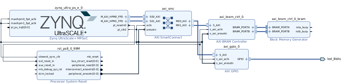
ZCU102 Configurable Example Design (CED) base block design.
PL Payload
Default Payload: Base Platform (No VCU)
AXI Interconnect fabric
GPIO controllers for LEDs/switches
PL DDR4 controller
Interrupt controller
IIC controller for I2C devices
Additional Payloads Available:
Targeted Reference Designs (TRDs):
Image processing pipeline
PCIe DMA example
Ethernet packet processor
Custom accelerator templates
Example Designs:
AXI DMA loopback
Video pass-through (through FMC)
Sensor interfacing
AI/ML inference engine
PS Specifications
Processing System Configuration:
ZCU102 PS Peripheral Mappings in the CED
Peripheral |
MIO Pins |
Function |
|---|---|---|
SD1 |
MIO39-51 |
SD Card boot/storage |
USB0 |
MIO52-63 |
USB 3.0 host/device |
GEM3 |
MIO64-77 |
Gigabit Ethernet |
UART0 |
MIO18-19 |
Console UART |
UART1 |
MIO20-21 |
Debug UART |
I2C0 |
MIO14-15 |
I2C bus 0 |
I2C1 |
MIO16-17 |
I2C bus 1 |
GPIO |
MIO0-13, 22-37 |
General purpose I/O |
Interrupts
PS Interrupt Controller (GIC-400):
16 SGIs (Software Generated)
16 PPIs (Private Peripheral)
64 SPIs (Shared Peripheral)
Key Interrupt Mappings:
IRQ |
Source |
Description |
|---|---|---|
121 |
PL[0] |
|
122 |
PL[1] |
|
123-136 |
PL[2-15] |
Additional PL interrupts |
57 |
GEM3 |
Ethernet |
48 |
SD1 |
SD Card |
65 |
USB0 |
USB 3.0 |
PS-PL Interrupts
Available PL to PS Interrupts:
16 interrupts (PL[0:15])
IRQ 121-136 in GIC
Rising edge or level sensitive
Routed through AXI interrupt controller
Typical Usage:
PL[0]: AXI Interrupt Controller output
PL[1]: Direct GPIO interrupt
PL[2-15]: Available for custom IP
IPI Mappings
Inter-Processor Interrupts:
IPI Channel |
Source |
Target |
Usage |
|---|---|---|---|
IPI0 |
|||
IPI1 |
|||
IPI2 |
PMU |
Power management requests |
|
IPI3 |
PMU |
Power event notifications |
DDR Memory Map
Start Address |
End Address |
Size |
Description |
Interface |
|---|---|---|---|---|
0x0000_0000 |
0xFFFF_FFFF |
4 GB |
PS DDR4 |
64-bit |
0x0004_0000_0000 |
0x0004_1FFF_FFFF |
512 MB |
PL DDR4 |
16-bit |
System Level Memory Map
Address Range |
Size |
Description |
|---|---|---|
0x0000_0000 - 0xFFFF_FFFF |
4 GB |
PS DDR4 |
0x0004_0000_0000 - 0x0004_1FFF_FFFF |
512 MB |
PL DDR4 |
0x8000_0000 - 0xBFFF_FFFF |
1 GB |
PL Address Space (M_AXI_GP0/1) |
0xA000_0000 - 0xA000_FFFF |
64 KB |
GPIO Controllers |
0xA001_0000 - 0xA001_FFFF |
64 KB |
AXI Interrupt Controller |
0xA002_0000 - 0x |
ZCU106

The AMD ZCU106 evaluation board.
Default Boot Flow
The default boot flow for the EDF Linux BSP for ZCU106 is Common Specifications
See Common Specifications for more information.
ZCU106 Boot Firmware and Linux Disk Images
Boot Firmware Images
Not applicable
Linux Disk Image - Common Disk Image With Support for This Board
edf-platform-disk-image-amd-cortexa53-mali-common+zynqmp-zcu106-multidomain.rootfs.wic.xz
Advanced Embedded Software Configurations Included
Xen Dom0 (through
edf-platform-disk-image; see image-variant comparison)OpenAMP runtime packages (through
edf-platform-disk-image); per-board firmware example tarballs to follow in EDF 26.1.1xen-zephyr-domu-imageZephyr DomU payload to follow in EDF 26.2
UART Connections - FTDI-USB
Channel |
Device Node |
Function |
Settings |
PS Connection |
|---|---|---|---|---|
UART0 |
/dev/ttyUSB0 |
PS Console |
115200,8,N,1 |
MIO18-19 |
UART1 |
/dev/ttyUSB1 |
PMU/FSBL Debug |
115200,8,N,1 |
MIO20-21 |
UART2 |
/dev/ttyUSB2 |
VCU Debug |
115200,8,N,1 |
EMIO |
UART3 |
/dev/ttyUSB3 |
115200,8,N,1 |
EMIO |
ZCU106 Ethernet Connections
PS Ethernet (GEM3):
Type: 10/100/1000 Mb/s
PHY: TI DP83867Connector: RJ45
MIO: PS Bank 501 (MIO64-77)
PL Ethernet:
Type: 10 Gigabit Ethernet
Interface: SFP+ cage
IP Core: 10G/25G Ethernet Subsystem
GTH Transceivers: Bank 224
Configuration:
# Linux interfaces
eth0: PS GEM3 (1GbE)
eth1: PL 10GbE SFP+
ZCU106 Base Design (CED) and PS Specifications
CED Block Design:
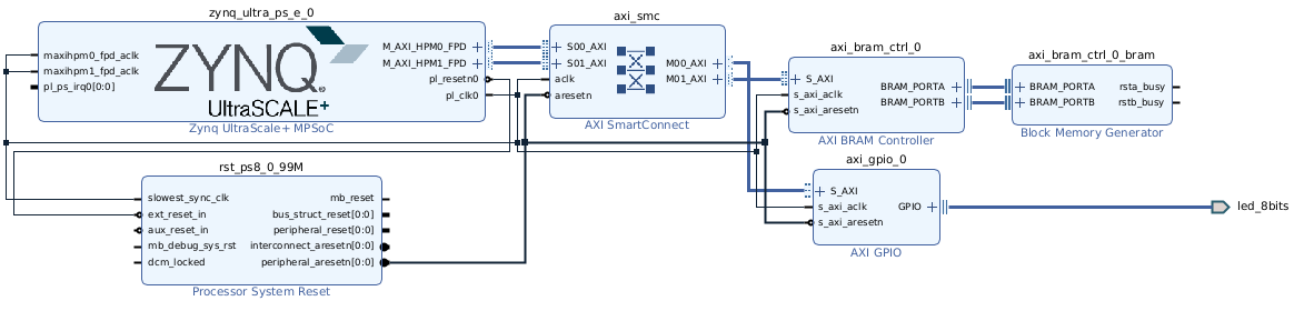
ZCU106 Configurable Example Design (CED) base block design.
PL Payload
Default Payload: VCU Extensible Platform
VCU Components:
H.264/H.265 encoder (4Kp60)
H.264/H.265 decoder (4Kp60)
Multi-stream support (8x 1080p30)
Low latency mode support
Video I/O:
HDMI 2.0 RX (up to 4Kp60)
HDMI 2.0 TX (up to 4Kp60)
SDI support through FMC card
Memory Infrastructure:
Frame buffers in PL DDR4
DMA engines for video data
Memory controller optimization
Additional Payloads Available:
PS Specifications
Processing System Configuration:
ZCU106 PS Peripheral Mappings in the CED
Peripheral |
MIO Pins |
Function |
|---|---|---|
SD1 |
MIO39-51 |
SD Card boot/storage |
USB0 |
MIO52-63 |
USB 3.0 host/device |
GEM3 |
MIO64-77 |
Gigabit Ethernet |
UART0 |
MIO18-19 |
Console UART |
UART1 |
MIO20-21 |
Debug UART |
I2C0 |
MIO14-15 |
I2C bus 0 (HDMI) |
I2C1 |
MIO16-17 |
I2C bus 1 (SFP+) |
GPIO |
MIO0-13, 22-37 |
General purpose I/O |
DP |
MIO27-30 |
DisplayPort AUX |
Interrupts
PS Interrupt Controller (GIC-400):
IRQ Range |
Source |
Count |
|---|---|---|
0-15 |
SGI |
16 |
16-31 |
PPI |
16 |
32-95 |
SPI |
64 |
121-136 |
16 |
VCU-Specific Interrupts:
IRQ |
Source |
Description |
|---|---|---|
104 |
VCU_ENC |
VCU encoder interrupt |
105 |
VCU_DEC |
VCU decoder interrupt |
106 |
VCU_MCU |
VCU MCU interrupt |
PS-PL Interrupts
PL to PS Interrupt Allocation:
Interrupt |
Source |
Usage |
|---|---|---|
PL[0] |
AXI INTC |
Aggregated PL interrupts |
PL[1] |
HDMI RX |
HDMI receive events |
PL[2] |
HDMI TX |
HDMI transmit events |
PL[3] |
10GbE |
10G Ethernet |
PL[4] |
V_FRMBUF_WR |
Frame buffer write complete |
PL[5] |
V_FR |
VPK180

The AMD VPK180 evaluation board.
Boot Firmware and Linux Disk Images
Boot Firmware Images - QSPI VPK180 - Boot Firmware + boot.bin:
Refer to Common Specifications
Linux Disk Image - Common Disk Image With Support for This Board
Refer to Common Specifications. For the SD card partition layout used as the secondary boot device, see EDF Disk Image Layout.
Advanced Embedded Software Configurations Included
Xen Dom0 (through
edf-platform-disk-image; see image-variant comparison)The platform image installs the Linux OpenAMP runtime packages but does not ship a prebuilt VPK180 RPU firmware example for Linux to load with
remoteproc. Skip OpenAMP demo steps that load an RPU firmware ELF on the VPK180 platform image, or build and install the firmware yourself first.xen-zephyr-domu-imageZephyr DomU payload to follow in EDF 26.2
DDR Memory Map
The four DDR controllers (C0 - C3) each map their per-channel windows into the same shared LPDDR4 address regions. Access is interleaved across controllers by the NoC.
Start Address |
End Address |
Size |
Description |
Interface |
Access Type |
|---|---|---|---|---|---|
0x0000_0000_0000 |
0x0007_FFFF_FFFF |
2 GB |
C0_DDR_LOW0 |
NoC_lpddr0/S00_INI |
R/W |
0x0008_0000_0000 |
0x000F_FFFF_FFFF |
2 GB |
C0_DDR_LOW1 |
NoC_lpddr0/S00_INI |
R/W |
0x0500_0000_0000 |
0x0500_FFFF_FFFF |
4 GB |
C0_DDR_CH1 |
NoC_lpddr1/S00_INI |
R/W |
0x0600_0000_0000 |
0x0600_FFFF_FFFF |
4 GB |
C0_DDR_CH2 |
NoC_lpddr2/S00_INI |
R/W |
0x0500_0000_0000 |
0x0500_FFFF_FFFF |
4 GB |
C1_DDR_CH1 |
NoC_lpddr1/S01_INI |
R/W |
0x0600_0000_0000 |
0x0600_FFFF_FFFF |
4 GB |
C1_DDR_CH2 |
NoC_lpddr2/S01_INI |
R/W |
0x0500_0000_0000 |
0x0500_FFFF_FFFF |
4 GB |
C2_DDR_CH1 |
NoC_lpddr0/S02_INI |
R/W |
0x0600_0000_0000 |
0x0600_FFFF_FFFF |
4 GB |
C2_DDR_CH2 |
NoC_lpddr0/S02_INI |
R/W |
0x0500_0000_0000 |
0x0500_FFFF_FFFF |
4 GB |
C3_DDR_CH1 |
NoC_lpddr0/S03_INI |
R/W |
0x0600_0000_0000 |
0x0600_FFFF_FFFF |
4 GB |
C3_DDR_CH2 |
NoC_lpddr0/S03_INI |
R/W |
The DDR configuration is summarized as follows:
Total DDR: Multiple LPDDR4 component memories
Channel Configuration: 3 memory controllers, multiple channels
Memory Type: LPDDR4
Access: Through NoC (Network on Chip)
System Level Memory Map
Start Address |
Description |
Size |
Type |
|---|---|---|---|
0x0000_0000_0000 |
DDR Low Memory Region 0 |
2 GB |
DDR |
0x0008_0000_0000 |
DDR Low Memory Region 1 |
2 GB |
DDR |
0x0500_0000_0000 |
DDR Channel 1 (All Controllers) |
4 GB |
DDR |
0x0600_0000_0000 |
DDR Channel 2 (All Controllers) |
4 GB |
DDR |
0xA400_0000 |
AXI Block RAM Controller |
8 KB |
|
0xA401_0000 |
AXI GPIO 0 (LEDs) |
64 KB |
PL Peripheral |
0xA402_0000 |
AXI GPIO 1 (Push Buttons) |
64 KB |
PL Peripheral |
0xA403_0000 |
AXI GPIO 2 (DIP Switches) |
64 KB |
PL Peripheral |
0xF000_0000 |
CIPS Configuration Space |
PS Registers |
|
0xF100_0000 |
FPD Peripherals |
PS Peripherals |
|
0xF900_0000 |
LPD Peripherals |
PS Peripherals |
|
0xFE00_0000 |
PMC Peripherals |
||
0xFF00_0000 |
CPM / PCIe |
CPM |
Programmable Logic Peripheral Details
The following table provides a focused PL-peripheral view and repeats the same BRAM and GPIO base addresses listed in the preceding system memory map.
Base Address |
Peripheral |
Description |
Size |
|---|---|---|---|
0xA400_0000 |
BRAM storage |
8 KB |
|
0xA401_0000 |
GPIO_0 |
LED control (gpio_led) |
64 KB |
0xA402_0000 |
GPIO_1 |
Push buttons (gpio_pb) |
64 KB |
0xA403_0000 |
GPIO_2 |
DIP switches (gpio_dp) |
64 KB |
VPK180 QSPI Memory Map
The VPK180 multidomain machine uses the edf-qspi recipe with the 256 MB
QSPI flash.
Start Address |
Description |
Size |
Source |
Purpose |
|---|---|---|---|---|
0x0000_0000 |
Image selector, primary |
384 KB |
|
Initial boot selection |
0x0006_0000 |
Image selector, backup |
384 KB |
|
Backup boot selection |
0x000C_0000 |
Image selector scratch |
128 KB |
Empty |
Reserved scratch space |
0x000E_0000 |
Image recovery |
20 MB |
|
Recovery boot image |
0x014E_0000 |
Image recovery scratch |
128 KB |
Empty |
Reserved scratch space |
0x0150_0000 |
Update metadata, primary |
128 KB |
|
Primary firmware update metadata |
0x0152_0000 |
Update metadata, backup |
128 KB |
|
Backup firmware update metadata |
0x0154_0000 |
U-Boot environment, primary |
128 KB |
Empty |
Reserved environment space |
0x0156_0000 |
U-Boot environment, backup |
128 KB |
Empty |
Reserved environment space |
0x0158_0000 |
Reserved / unallocated |
256 KB |
Empty |
Reserved space |
0x015C_0000 |
|
114.25 MB |
|
Primary boot firmware image |
0x0880_0000 |
|
114.25 MB |
|
Backup boot firmware image |
0x0FA4_0000 |
User scratch |
5.69 MB |
Empty |
Reserved user scratch space |
0x0FFF_0000 |
Manifest |
64 KB |
Manifest generated by |
QSPI image manifest |
Programming Secondary Boot Media
See Discovery and Evaluation
for writing the EDF Linux disk image (.wic) to an SD card.
Basic Board Interfaces
The board’s key interfaces, taken from the VPK180 block diagram, are grouped by function as follows:
- Memory
LPDDR4 component memory (3 controllers)
- High-Speed I/O
- Storage
SD 3.0 card interface
QSPI flash
- USB
USB 2.0 ULPI interface
- Networking
GEM (Gigabit Ethernet media access controller)
- Debug
JTAG interface
Mictor debug connector
- Expansion
FMC+ connector
GPIO headers
- Timing & Clocks
IEEE-1588 clock
SMA clock connectors
Powering the Board
The VPK180 main power input is:
Main Power Input: 12 V DC
The board’s power domains are:
Power sequencing is:
Controlled by system controller / PMC
Power indicators are:
Power-good LEDs
Default Boot Switch Settings
Boot Mode |
MODE[3:0] |
DIP Switch |
Description |
|---|---|---|---|
0000 |
SW1: OFF-OFF-OFF-OFF |
JTAG boot |
|
QSPI32 |
0010 |
SW1: OFF-OFF-ON-OFF |
QSPI boot |
SD1_LS |
1110 |
SW1: ON-ON-ON-OFF |
SD card boot |
USB |
0111 |
SW1: OFF-ON-ON-ON |
USB boot |
Note
Boot mode settings and switch numbering follow the VPK180 board user guide (UG1551).
System Controller Firmware Update
See the System Controller Updates Wiki page for more information.
Serial Console Connections Through USB Adapter
UART Channel |
Source |
Destination |
Purpose |
Default Settings |
|---|---|---|---|---|
UART0 |
PS MIO |
FTDI CH A |
Linux/APU Console |
115200,8,N,1 |
UART1 |
PMC MIO |
FTDI CH B |
PMC/PLM Console |
115200,8,N,1 |
UART2 |
EMIO |
FTDI CH C |
115200,8,N,1 |
|
UART3 |
FTDI CH D |
Spare / User |
115200,8,N,1 |
Base Vivado Design - Board Support Package and PS Specifications
This specification inherits from the common and device specific specifications, but also has evaluation board specific items. See also the following:
See Common Specifications for the embedded common platform Configurable Example Design (CED).
See Common Specifications for the Processing System (PS) common minimum specification.
PL Board I/O
Programmable Logic Input and Output Interfaces
Interface |
Type |
Location |
Description |
|---|---|---|---|
FMC+ Connector |
High-speed expansion |
PL banks |
FMC+ HPC compatible |
GPIO Headers |
Digital I/O |
PL banks |
General purpose |
EMIO Signals |
PS-PL interface |
XPIO |
Extended MIO |
Mictor Connector |
Debug |
PL banks |
High-speed |
SMA Connectors |
Clock / RF |
PL banks |
External clocks |
High-speed serial |
Dedicated |
Optical / FMC |
Programmable Logic Peripherals in Configurable Example Design
Controller |
Base Address |
Description |
Direction |
|---|---|---|---|
axi_gpio_0 |
0xA401_0000 |
GPIO LEDs |
Output |
axi_gpio_1 |
0xA402_0000 |
GPIO Push Buttons |
Input |
axi_gpio_2 |
0xA403_0000 |
GPIO DIP Switches |
Input |
axi_bram_ctrl_0 |
0xA400_0000 |
BRAM Controller |
Bidirectional |
Memory Map Interface Configuration
Memory Map Interface Clocks
Reference Programmable Logic Payload Information
See the Discovery and Evaluation
Enabling Secure Mode Flag in Boot Arguments
The versal_sysmon.secure_mode=1 kernel command-line flag enforces
secure access control on the Versal SYSMON interface. Enable
it for platform validation, secure production images, and environments
where System Monitor interfaces must follow secure-mode restrictions.
By default, versal_sysmon.secure_mode=1 is not enabled in
built images. To enable it, use the kernel command-line modification
workflow described in Setting Kernel Boot Arguments.
After the build completes, apply the flag by modifying
loader/entries/edf-linux.conf in the .wic image using
wic cp (extract, edit, and copy back).
Append the following argument to
the options line of edf-linux.conf:
versal_sysmon.secure_mode=1
After flashing the updated .wic image and booting the board,
verify the flag is active. The exact versal-sysmon driver message
varies by kernel version:
amd-edf:/home/amd-edf# cat /proc/cmdline
... versal_sysmon.secure_mode=1 ...
amd-edf:/home/amd-edf# dmesg | grep -i sysmon
versal-sysmon ...: secure mode enabled
On other Versal boards that require the same flag, use the same workflow with that board’s image artifact name.
ZCU208

The AMD ZCU208.
Default Boot Flow
The default boot flow for the EDF Linux BSP for ZCU208 follows the single-stage boot described in Common Specifications.
ZCU208 Boot Firmware and Linux Disk Images
Boot Firmware Images
Not applicable
Linux Disk Image - Common Disk Image With Support for This Board
edf-platform-disk-image-amd-cortexa53-common+zynqmp-zcu208-multidomain.rootfs.wic.xz
ZCU208 base design (CED) and PS specifications
The ZCU208 uses the same Zynq UltraScale+ embedded common platform CED as the other RFSoC boards; refer to ZCU111 for the block design and the PS configuration.
KV260

The AMD KV260.
Default Boot Flow
The KV260 boots in two stages: EDF boot firmware in the QSPI flash on the SoM, and the root filesystem on an SD card. See Kria SoM in Common Specifications, and the QSPI + SD walkthrough on the discovery page.
KV260 Boot Firmware and Disk Images
Boot Firmware Images
BOOT-k26-smk-kv-sdt-multidomain.bin, built from thekria-qspirecipe
Disk Image - Common Kria Image With Support for This Board
edf-platform-disk-image-kria-amd-cortexa53-mali-common.rootfs.wic.xzOne image serves every supported Kria SoM variant. It is a different recipe from the
edf-platform-disk-imagethe evaluation boards use.
Machines
k26-smk-kv-sdt- Linux onlyk26-smk-kv-sdt-multidomain- multi-domain
The base design is kria_base/k26/kv260_base in the
AMD Yocto hardware platforms repository.
KR260

The AMD KR260.
Default Boot Flow
The KR260 boots in two stages: EDF boot firmware in the QSPI flash on the SoM, and the root filesystem on an SD card. See Kria SoM in Common Specifications, and the QSPI + SD walkthrough on the discovery page.
KR260 Boot Firmware and Disk Images
Boot Firmware Images
BOOT-k26-smk-kr-sdt-multidomain.bin, built from thekria-qspirecipe
Disk Image - Common Kria Image With Support for This Board
edf-platform-disk-image-kria-amd-cortexa53-mali-common.rootfs.wic.xzOne image serves every supported Kria SoM variant. It is a different recipe from the
edf-platform-disk-imagethe evaluation boards use.
Machines
k26-smk-kr-sdt- Linux onlyk26-smk-kr-sdt-multidomain- multi-domain
The base design is kria_base/k26/kr260_base in the
AMD Yocto hardware platforms repository.
KD240

The AMD KD240.
Default Boot Flow
The KD240 boots in two stages: EDF boot firmware in the QSPI flash on the SoM, and the root filesystem on an SD card. See Kria SoM in Common Specifications, and the QSPI + SD walkthrough on the discovery page.
KD240 Boot Firmware and Disk Images
Boot Firmware Images
BOOT-k24-smk-kd-sdt-multidomain.bin, built from thekria-qspirecipe
Disk Image - Common Kria Image With Support for This Board
edf-platform-disk-image-kria-amd-cortexa53-mali-common.rootfs.wic.xzOne image serves every supported Kria SoM variant. It is a different recipe from the
edf-platform-disk-imagethe evaluation boards use.
Machines
k24-smk-kd-sdt- Linux onlyk24-smk-kd-sdt-multidomain- multi-domain
The base design is kria_base/k24/kd240_base in the
AMD Yocto hardware platforms repository.
VRK165
Note
The versal-vrk165-revb-sdt-seg and
versal-vrk165-revb-multidomain machines (VRK165 Rev B) use the
same board hardware specifications documented in this section.
Default Boot Flow
The VRK165 uses the EDF default multi-stage boot: EDF boot firmware in OSPI, with the disk image on the secondary boot media. See Common Specifications.
VRK165 Boot Firmware and Linux Disk Images
Boot Firmware Images
edf-ospi-versal-vrk165-multidomain.bin
EDF v26.11 publishes no prebuilt OSPI boot firmware
for the Rev B board. Build it with bitbake edf-ospi against
versal-vrk165-revb-multidomain.
Linux Disk Image - Common Disk Image With Support for This Board
Refer to Common Specifications.
VRK165 base design (CED) and PS specifications
The design is eval_board_base/vrk165_base in the AMD Yocto
hardware platforms repository. Its
gen_sdt.tcl passes versal-vrk160-reva.dtsi, which is the VRK160 Rev A
include and is shared across the VRK family rather than being a
copy-paste error.
The design is eval_board_base/vrk165_revb_base in the AMD Yocto
hardware platforms repository. Its
gen_sdt.tcl passes versal-vrk160-reva.dtsi, which is the VRK160 Rev A
include and is shared across the VRK family rather than being a
copy-paste error.
VMK365
Default Boot Flow
The default boot flow for the EDF Linux BSP for VMK365 is the single-stage boot with deferred PL load described in Common Specifications.
VMK365 Boot Firmware and Linux Disk Images
EDF v26.11 builds boot components for the VMK365 and publishes no bootable prebuilt image for it. Build the image for your board instead; see Operating System Integration and Development.
Machines
versal-2ve-2vm-vmk365-sdt-seg- Linux onlyversal-2ve-2vm-vmk365-multidomain- multi-domain
VMK365 base design (CED) and PS specifications
The design is eval_board_base/vmk365_base in the AMD Yocto
hardware platforms repository.
VM-P-M1369
Default Boot Flow
The default boot flow for the EDF Linux BSP for the VM-P-M1369 is the single-stage boot with deferred PL load described in Common Specifications.
VM-P-M1369 Boot Firmware and Linux Disk Images
Boot Firmware Images
Not applicable
Linux Disk Image - Common Disk Image With Support for This Board
edf-platform-disk-image-amd-cortexa72-common+versal-vm-p-m1369-00-reva-x-prc-01-reva-multidomain.rootfs.wic.xz
Machines
versal-vm-p-m1369-00-reva-x-prc-01-reva-sdt-seg- Linux onlyversal-vm-p-m1369-00-reva-x-prc-01-reva-multidomain- multi-domain
VM-P-M1369 base design (CED) and PS specifications
The design is eval_board_base/vm-p-m1369-00_base in the AMD Yocto
hardware platforms repository.
Note
AMD publishes no photograph of this board, so none is shown here rather than showing a different board in its place.
K24C and K24I

The AMD Kria K24 System-on-Module.
Default Boot Flow
The K24C and K24I are bare SoM modules. They boot in a single stage from an SD card with the PL loaded after Linux starts; see Kria SoM.
Boot Firmware and Disk Images
EDF v26.11 publishes no prebuilt image for either module. The release builds prebuilt artifacts for the starter kits only. See Booting a Bare System-on-Module.
Machines
k24c-sm-sdt- K24C, the commercial-grade modulek24i-sm-sdt- K24I, the industrial-grade module
Base design
The Kria module designs are under kria_base/k24/ in the AMD Yocto
hardware platforms repository. That directory
separates designs by carrier board and silicon grade while these
machines do not, so no single design is named here; read the directory
and pick the one matching your carrier.
K26C
Default Boot Flow
The K26C is a bare SoM module. It boots in a single stage from an SD card with the PL loaded after Linux starts; see Kria SoM.
Boot Firmware and Disk Images
EDF v26.11 publishes no prebuilt image for the K26C. The release builds prebuilt artifacts for the starter kits only. See Booting a Bare System-on-Module.
Machines
k26-sm-sdt. The machine is not split by silicon grade, so the same one serves the commercial and the industrial module.
Base design
The K26 module designs are under kria_base/k26/ in the AMD Yocto
hardware platforms repository.
Note
AMD publishes no photograph of the bare K26 module, so none is shown here rather than showing a starter kit in its place.
SCU200
The SCU200 carries a MicroBlaze V (RISC-V) soft processor implemented in programmable logic rather than a hardened application processor. The supported Zephyr design uses a 32-bit MicroBlaze V core.
See Building and Booting Zephyr Hello World on the SCU200 Platform for
the mbv32-scu200-zephyr-sdt machine, build artifacts, and
JTAG boot procedure.
VPK360
Boot Firmware and Linux Disk Images
The VPK360 supports both Linux-only and multidomain machine
configurations. The Linux-only flow uses
versal-2vp-vpk360-sdt-seg with the xilinx-bootbin recipe.
The multidomain flow uses versal-2vp-vpk360-multidomain with the
edf-ospi recipe.
This gives one board profile with two deployment modes. Choose Linux-only or multidomain based on your target image.
Base Platform CED Alignment
This section defines the VPK360 common evaluation design (CED) specification. It focuses on platform differences relative to the VEK385-based common specification.
The VPK360 base-platform definition follows the shared EDF base CED model used across Versal platforms. In this model, the base CED is the reference for PS subsystem settings. It also defines DDR memory controller (DDRMC) and hard-block path configuration for boot firmware.
VPK360 serves as a reference platform for MIPI examples on the FMC connector, covering both D-PHY and C-PHY use cases. VPK360 targets high-bandwidth networking and multimedia accelerator workflows.
DDR Memory Controller Configuration
The VPK360 includes five LPDDR5 DDR memory controller instances. All five use 1x32 single-rank mode with internal clocks.
Physical Controller |
I/O Banks |
DDR Config |
MC Config |
Footprint |
Primary Function |
Clock |
NoC Remap |
DDRMC Optimization |
|---|---|---|---|---|---|---|---|---|
DDRMC0 |
700/701/702 |
1x32, single rank |
Interleaved with DDRMC1 |
4 GB |
PS subsystem |
Internal - HSM1 |
No |
Random access pattern |
DDRMC1 |
704/705 |
1x32, single rank |
Interleaved with DDRMC0 |
4 GB |
PS subsystem |
Internal - HSM1 |
No |
Random access pattern |
DDRMC2 |
712/713 |
1x32, single rank |
Interleaved with DDRMC3 |
4 GB |
PL accelerators/offloads |
Internal - HSM1 |
No |
Linear/sequential access pattern |
DDRMC3 |
716/717 |
1x32, single rank |
Interleaved with DDRMC2 |
4 GB |
PL accelerators/offloads |
Internal - HSM1 |
No |
Linear/sequential access pattern |
DDRMC4 |
718/719 |
1x32, single rank |
Non-interleaved |
4 GB |
PL accelerators/offloads |
Internal - HSM1 |
No |
Random access pattern |
MIO and Multimedia Interface Peripheral Configuration
The following table lists VPK360 MIO and multimedia interface defaults. The CED configures any unassigned PMC or PS MIO pin as GPIO.
Functional Interface |
MIO Pins |
Notes |
|---|---|---|
OSPI |
PMC MIO[0-10], PMC MIO[12] |
PMC MIO[11] is GPIO |
USB |
PMC MIO[13-25] |
USB0 controller |
SD Card (SDIO) |
PMC MIO[26-36], PMC MIO[51] |
|
PMC I2C |
PMC MIO[38-39] |
|
LPD I2C0 |
PMC MIO[42-43] |
PS I2C0 controller |
LPD I2C1 |
PMC MIO[44-45] |
|
UART1 |
PMC MIO[46-47] |
PS UART1 |
GEM |
PS MIO[0-11], PS MIO[24-25] |
GEM0 controller plus MDIO |
System Monitor remote access |
PS MIO[13-14] |
Disabled by default in the design |
UART0 |
PS MIO[16-17] |
Linux console ( |
TTC |
PS MIO[22-23] |
Fan PWM, driven by a TTC wave output; assigned on the board rather than in the CED |
Boot Firmware Images - OSPI VPK360 - Boot Firmware + boot.pdi
Refer to Common Specifications.
Linux Disk Image - Common Disk Image With Support for This Board
VPK360 uses the Cortex-A72 common Linux disk image,
amd-cortexa72-common. Although VPK360 belongs to the Versal Gen 2
family, its APU is Cortex-A72; select the A72 image rather than the
Cortex-A78 image used by VEK385, VEK386, and VMK365.
For hardware evaluation, obtain the
edf-platform-disk-image-amd-cortexa72-common.rootfs-<timestamp>.wic.xz
image and matching .wic.bmap from Downloads.
For the QEMU build and wic.qemu-sd image, follow
Building Images for QEMU.
OSPI Memory Map
The VPK360 device tree defines the OSPI controller mapping as
spi0 = &ospi and places the controller at address 0xF101_0000.
The boot-image partitioning model follows the standard edf-ospi
layout used by the prebuilt VPK360 flows.
Item |
Value from system-top.dts |
|---|---|
Boot flash interface mapping |
|
Controller node |
|
Controller base address |
0xF101_0000 |
Primary console at boot |
|
DDR Memory Map
The VPK360 device tree source exposes three NoC DDR memory nodes. Their
reg windows decode to:
Start Address |
End Address |
Size |
Description |
|---|---|---|---|
0x0000_0000 |
0x7FFF_FFFF |
2 GB |
NoC_C0_C1 DDR low window |
0x0008_0000_0000 |
0x0009_7FFF_FFFF |
6 GB |
NoC_C0_C1 DDR high window |
0x0500_0000_0000 |
0x0501_FFFF_FFFF |
8 GB |
NoC_C2_C3 DDR window |
0x0600_0000_0000 |
0x0600_FFFF_FFFF |
4 GB |
NoC_C4 DDR window |
The total DDR window visible from these nodes is 20 GB.
System Level Memory Map
The following system-level mappings are present in system-top.dts
for VPK360:
Address Range |
Description |
|---|---|
0x0000_0000 - 0x7FFF_FFFF |
DDR low memory |
0x0008_0000_0000 - 0x0009_7FFF_FFFF |
DDR high memory |
0x0500_0000_0000 - 0x0501_FFFF_FFFF |
DDR C2/C3 region |
0x0600_0000_0000 - 0x0600_FFFF_FFFF |
DDR C4 region |
0xFC00_0000 - 0xFCFF_FFFF |
CPM6 peripheral window |
0xFD00_0000 - 0xFDFF_FFFF |
CCI/FPD and related control region |
0xFF00_0000 - 0xFF3F_FFFF |
LPD UART/I2C/GPIO/GEM and timer peripherals |
Processing Subsystem Topology
The VPK360 system device tree declares the following processing clusters:
cpus-a72@0(A72 cluster)cpus-r5@0andcpus-r5@1(R5 clusters)cpus_microblaze@0andcpus_microblaze@1
Primary Peripheral Mappings
Device tree name |
Bound node |
Typical use |
|---|---|---|
|
|
Primary Linux console |
|
|
Secondary UART |
|
|
Boot flash |
|
|
Board I2C buses |
|
|
Gigabit Ethernet media access controller |
Programming and Flashing
For VPK360 OSPI firmware, SD-card preparation, and boot steps, see VPK360: Booting With OSPI Firmware and an SD Disk Image. For building the multidomain firmware, see Creating a Multi-stage Boot Image.
Serial and Ethernet Notes
Default console is
serial0at115200n8.Ethernet mapping
ethernet0points togem0.The system device tree mapping block also exposes
serial1,i2c0,i2c1, andspi0for board integration.
Advanced Embedded Software Configurations Included
The multidomain VPK360 flow includes OpenAMP, Xen, and system-ready image-recovery support.
VEK386
Boot Firmware and Linux Disk Images
The VEK386 supports both Linux-only and multidomain machine
configurations. The Linux-only flow uses
versal-2ve-2vm-vek386-sdt-seg with the xilinx-bootbin recipe,
and the multidomain flow uses
versal-2ve-2vm-vek386-multidomain with the edf-ospi recipe.
Base Platform CED Alignment
This section defines the VEK386 common evaluation design (CED) specification. It focuses on platform differences relative to the VEK385-based common specification.
Functionally, VEK386 is equivalent to VEK385, with minimal changes required to support the new device package while keeping board behavior aligned with VEK385.
DDR Memory Controller Configuration
VEK386 LPDDR5 DDR memory controller configuration matches the VEK385 definition from the common CED specification.
MIO and Multimedia Interface Peripheral Configuration
VEK386 MIO and multimedia interface peripheral configuration matches the VEK385 definition from the common CED specification.
Boot Firmware Images - OSPI VEK386 - Boot Firmware + boot.pdi
Refer to Common Specifications.
Linux Disk Image - Common Disk Image With Support for This Board
Refer to Common Specifications.
OSPI Memory Map
The VEK386 device tree defines the OSPI controller mapping as
spi0 = &ospi and maps the controller at 0xF101_0000. The
edf-ospi machine flow uses the common A/B and recovery partition
model documented in the common specifications.
Item |
Value from system-top.dts |
|---|---|
Boot flash interface mapping |
|
Controller node |
|
Controller base address |
0xF101_0000 |
Primary console at boot |
|
DDR Memory Map
The VEK386 device tree source also exposes three NoC DDR memory nodes. These nodes use the same decoded windows:
Start Address |
End Address |
Size |
Description |
|---|---|---|---|
0x0000_0000 |
0x7FFF_FFFF |
2 GB |
NoC_C0_C1 DDR low window |
0x0008_0000_0000 |
0x0009_7FFF_FFFF |
6 GB |
NoC_C0_C1 DDR high window |
0x0500_0000_0000 |
0x0501_FFFF_FFFF |
8 GB |
NoC_C2_C3 DDR window |
0x0600_0000_0000 |
0x0600_FFFF_FFFF |
4 GB |
NoC_C4 DDR window |
The total DDR window visible from these nodes is 20 GB.
System Level Memory Map
The VEK386 system-top.dts includes additional Versal Gen 2 system
windows. A78/R52 clusters and platform peripherals use these windows:
Address Range |
Description |
|---|---|
0x0000_0000 - 0x7FFF_FFFF |
DDR low memory |
0x0008_0000_0000 - 0x0009_7FFF_FFFF |
DDR high memory |
0x0500_0000_0000 - 0x0501_FFFF_FFFF |
DDR C2/C3 region |
0x0600_0000_0000 - 0x0600_FFFF_FFFF |
DDR C4 region |
0xE200_0000 - 0xE23F_FFFF |
GIC A78 region |
0xEB40_0000 - 0xEBFF_FFFF |
LPD controls, R52 TCM windows, DMA and system peripherals |
0xF100_0000 - 0xF1FF_FFFF |
PMC/LPD I/O peripherals (I2C, UART, CAN, GEM, USB, TTC) |
Processing Subsystem Topology
The VEK386 system device tree declares the following processing clusters:
cpus-a78@0(A78 cluster)cpus-r52@0throughcpus-r52@9(R52 clusters)cpus_microblaze@0
Primary Peripheral Mappings
Device tree name |
Bound node |
Typical use |
|---|---|---|
|
|
Primary Linux console |
|
|
Secondary UART |
|
|
Boot flash |
|
|
Board I2C buses |
|
|
Gigabit Ethernet media access controller |
Programming and Flashing
For primary boot-device programming and image-recovery flows, see:
For SD-card image preparation (.wic), see:
Serial, Ethernet, and I/O Notes
Default console is
serial0at115200n8.Ethernet mapping
ethernet0points togem0.The SDT includes CAN controllers (
can0throughcan3) and dual USB controller windows (usb1anddwc3_1mappings).
Advanced Embedded Software Configurations Included
The VEK386 multidomain prebuilt machine includes OpenAMP and system-ready image-recovery support, but does not enable Xen.